Selecting the wrong copper wire can quietly sabotage the performance of your toroidal transformer. I’ve seen it lead to excessive heat, signal loss, and even premature failure. These are issues no engineer or manufacturer wants in mission-critical systems like medical devices, solar panels, or smart electric meters.
The problem is, toroidal transformers are designed for efficiency and low electromagnetic interference, but these benefits depend heavily on the quality and specifications of the copper wire inside. It’s a detail that’s easy to overlook, yet it plays a major role in safety, durability, and performance.
In this blog, I’ll help you cut through the confusion and choose the right copper wire. Whether you’re designing for energy-efficient appliances or industrial control systems, the right wire will keep your transformer running cooler, lasting longer, and performing exactly as intended.
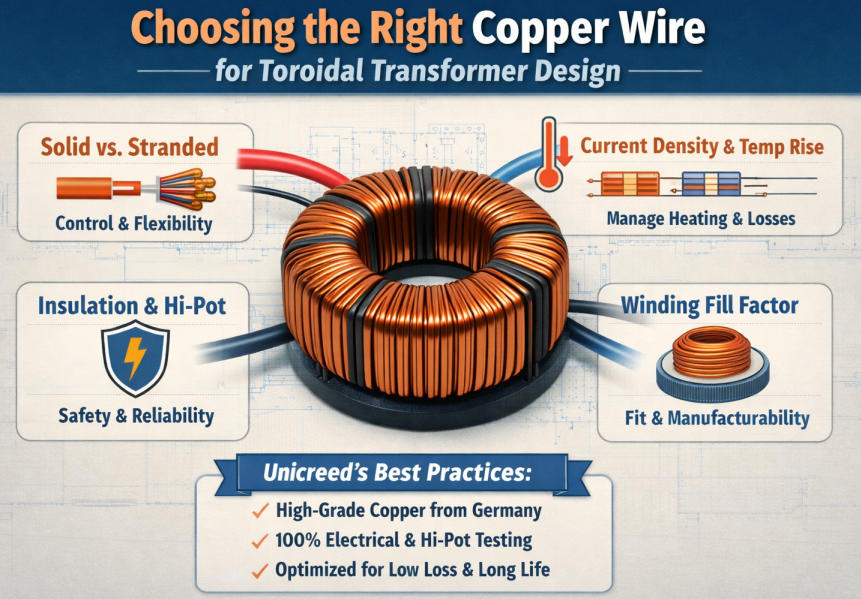
When designing a toroidal transformer, copper wire isn’t just a raw material. It is a core design choice that affects everything from performance to safety. Over the years, I’ve seen many engineers focus only on current ratings, missing critical factors like insulation grade, winding strategy, or regulatory compliance. To help you avoid costly oversights and design with confidence, I’ve summarized the most essential considerations into seven practical steps:
- Step 1, Define your load correctly (this decides current, wire size, and heat)
- Step 2, Pick conductor type: solid, stranded, or parallel wires (bifilar/multi-strand)
- Step 3, Choose wire size using current density + temperature rise, not only ampacity tables
- Step 4, Enamel insulation grade & build: the “hidden” reliability decision
- Step5, Skin effect at 50/60Hz: what matters and what doesn’t
- Step 6, Winding fill factor & manufacturability: design for what the line can repeat
- Step 7, Safety & compliance tie-in: wire choice impacts hi-pot and creepage outcomes
What copper wire options exist for toroidal transformers?
When it comes to winding toroidal transformers, not all copper wires are created equal. The shape, insulation, and construction of the wire can significantly affect how efficiently the transformer performs and how easy it is to manufacture. Based on the application and production needs, you have several copper wire options to choose from. Below, I will walk you through the most common types used in toroidal transformer design and when each one makes the most sense.
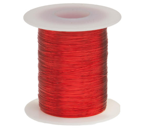
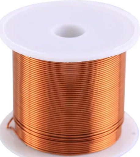
1.Enameled Copper Magnet Wire (Round)
This is the industry standard and default choice for most toroidal transformers. It is a single round conductor coated with a thin layer of enamel insulation.
Pros:
- Widely available and cost-effective
- Provides consistent insulation and performance
- Easy to source in a range of diameters
- Predictable behavior during automated or manual winding
Cons:
- As wire diameter increases, it becomes less flexible
- Thicker wires reduce fill factor, which can limit transformer efficiency in compact designs
This type of wire works well for low to moderate current applications at 50/60Hz, especially when space is not extremely tight.
2.Parallel Strands (Multi-Wire) vs. Single Thick Wire
When the required current is high and the wire gauge becomes large, a single thick wire can be difficult to wind around a toroidal core without stressing the enamel or causing damage. In such cases, using multiple thinner wires in parallel is a smart alternative.
Pros:
- Easier to bend and route around the toroid
- Better winding coverage and fill factor
- Lower mechanical stress during winding reduces risk of insulation failure
Cons:
- Each strand must be terminated consistently, which adds complexity
- Uneven current distribution (strand equalization issues) may occur without proper litz-style design
This approach is a practical solution when working with power toroids above a few hundred VA, where mechanical handling becomes a limiting factor.
3.Litz Wire (Use Only When Frequency Justifies It)
Litz wire is a specialty copper wire made of many individually insulated strands woven together. It is designed to minimize skin effect and proximity effect losses in high-frequency applications.
When to Use:
- High-frequency transformers or inductors, typically above 10 kHz
- Applications where efficiency at high frequencies is critical, such as in switching power supplies or RF systems
When Not to Use:
- Standard 50/60Hz power toroids do not benefit significantly from Litz wire
- Litz is more expensive and harder to terminate, so it is not recommended unless high frequency justifies the cost
Quick Note on Skin Effect:
At high frequencies, AC current tends to flow near the surface of the conductor. This increases effective resistance and power loss. Litz wire mitigates this by distributing the current across many small strands, each carrying current efficiently. For 50/60Hz toroidal transformers, however, skin effect is negligible, so standard magnet wire is typically sufficient.
Experience note:
In production, the “perfect” electrical wire can be a nightmare mechanically. A single very thick wire often causes uneven layers and local pressure points that later show up as audible hum or insulation wear.
Step1, Define your load correctly (this decides current, wire size, and heat)
Before choosing any wire size or insulation, you must start with a clear understanding of your load. This is where many transformer designs go wrong. If you misjudge the load type or duty conditions, every downstream decision from copper size to insulation class can be compromised. Let’s break down the key aspects that define your load accurately and set the foundation for a reliable toroidal transformer.
Step 1: Define Your Load Correctly
AC resistive load vs rectifier plus capacitor input load
AC load, the current waveform is smooth and sinusoidal, meaning the RMS current closely matches the average.
However, when powering a rectifier followed by a capacitor, which is common in DC power supplies, the current becomes highly pulsed. This increases the RMS current due to sharp charging peaks. If you size your copper wire based only on average current, the transformer will overheat. Always use true RMS current as your baseline when dealing with non-linear loads.
Continuous duty vs intermittent duty
The transformer’s load cycle has a major impact on copper wire selection. A unit operating continuously under full load, such as in 24-hour industrial use, requires thicker wire and stronger insulation to manage sustained heat buildup.
In contrast, a transformer that runs intermittently, for example 30 seconds on and 5 minutes off, can tolerate higher peak currents without overheating. Defining the correct duty cycle allows you to balance performance and material cost.
Ambient temperature and enclosure
Do not assume the transformer operates in open air at 25 degrees Celsius. Many industrial transformers are enclosed in sealed cabinets, where the ambient temperature can rise to 50 or even 70 degrees.
Higher ambient conditions reduce heat dissipation. If you do not account for this, even a well-sized copper wire may lead to insulation breakdown or reduced product lifespan.
Target temperature class
It is also important to define the appropriate insulation class. Class B, rated at 130 degrees Celsius, is widely used in industrial systems. It offers a good balance of thermal tolerance and cost efficiency.
If your transformer is exposed to high ambient temperatures or runs continuously at high power, consider Class F (155 degrees) or Class H (180 degrees). Choosing the right temperature class ensures your transformer remains reliable over time.
Experience note:
When customers tell us “V×I = VA”, we always ask if there is a bridge + bulk capacitor. In real projects, that’s where under-sized wire and overheating start.
Step 2,Pick conductor type: solid, stranded, or parallel wires (bifilar/multi-strand)
Once you understand your load requirements, the next critical decision is choosing the type of copper conductor. This choice directly affects how easy the transformer is to wind, how efficiently it performs, and how reliable it will be in the long term. Different applications and production methods may call for solid wire, stranded wire, or parallel wires. Let’s take a closer look at each option and when it makes the most sense.
Step 2: Pick Conductor Type
Solid Magnet Wire
Solid enameled copper wire is the most common conductor used in toroidal transformers. It offers excellent packing density and allows for precise turn control during winding. These properties are especially useful when space is limited or when consistent electrical parameters are required.
Advantages:
- Best winding fill factor for compact designs
- Easier to control number of turns accurately
- Ideal for lower to medium current applications
Limitations:
- As wire diameter increases, the wire becomes stiff and harder to bend
- Risk of enamel damage or fatigue cracking if bent too tightly, especially during manual winding
- Solid wire is usually the preferred option when current levels allow it and production consistency is a priority.
Stranded or Litz-like Conductor Approaches
For lower frequency toroidal transformers, true Litz wire is rarely used due to cost and complexity. However, stranded wires or Litz-style bundles are sometimes chosen for their flexibility and handling benefits.
When stranded wire helps
- Improved flexibility reduces the risk of insulation cracks during winding
- Easier to work with on thicker conductors where solid wire becomes too rigid
When stranded wire creates problems
- Lower packing efficiency compared to solid wire
- More difficult to terminate reliably, especially in tight spaces
- Greater variation in winding tension and consistency
Stranded wire is best used when winding large wire gauges or when mechanical handling during production is a concern.
Parallel Wires (Two-in-Hand or Three-in-Hand)
Instead of using one thick wire, many manufacturers prefer to run two or more thinner wires in parallel. This method balances current capacity with winding flexibility and helps avoid the problems of large single wires.
Advantages:
- Easier to wind than a single thick wire
- Less stress on enamel, which reduces damage rates
- Good option for medium to high power toroids
Manufacturing Note:
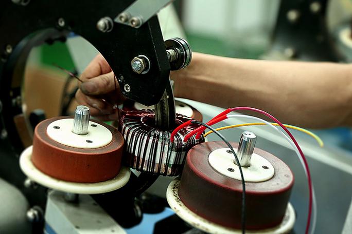
Toroidal winding applies constant tension to the wire. The stiffer the wire, the more force is required to wrap it, increasing the risk of insulation damage. Choosing a conductor that matches both the electrical and mechanical requirements of your process is essential for repeatable and high-quality productio
Experience note:
In our factory, a common issue with “too thick solid wire” is enamel scuffing during toroid winding especially on sharp core edges or when the winding shuttle tension is high.
Step 3, Choose wire size using current density + temperature rise, not only ampacity tables
After selecting the conductor type, the next critical step is choosing the correct wire size. Many designers make the mistake of relying only on standard ampacity tables—but toroidal transformers don’t operate in open-air test conditions. In real applications, the wire needs to handle both electrical current and thermal constraints within a confined space. That’s why I always size wire based on current density and expected temperature rise, then iterate for the best balance of performance and safety.
Step-by-Step Workflow: How I Do It
1.Estimate RMS Current (Primary & Secondary)
First, I calculate the RMS current for both windings based on the load. This is especially important when driving non-linear loads like rectifier-capacitor inputs, where the current waveform is peaky and not sinusoidal.
2.Set a Current Density Target
Instead of just picking a wire size from a table, I set a target current density, usually in the range of:
- 2.5–3.5 A/mm² for general industrial use
- <2.5 A/mm² for enclosed or continuous-duty systems
- 4 A/mm² only if intermittent duty or forced cooling is involved
If I’m working with higher ambient temperatures or potting, I always derate further.
3.Calculate Copper Loss (I²R) and Estimate Temperature Rise
Once I’ve chosen a wire size, I calculate the winding resistance and use it to find the copper loss (I²R). From there, I estimate the temperature rise based on core geometry, ventilation, and heat sinking.
If the rise is too high, I either increase the wire size or improve the winding layout.
4.Understand Toroid-Specific Heat Behavior
Toroids are more efficient in magnetic coupling than EI transformers, but that doesn’t mean they run cooler.
Key point:
Because toroids are compact and often enclosed, heat dissipation is limited. Winding tightly also makes it harder for air to circulate. That’s why wire sizing must always factor in thermal performance, not just electrical needs.
5.Apply Derating Rules
To stay safe and compliant, I apply these rules:
- Higher ambient = lower current density. (For example, 25°C ambient allows more current than 70°C inside a cabinet.)
- Potting or tight tape wrapping traps heat, so I reduce allowable current density by 10–20% in those cases.
Experience note:
By following this current density + temperature rise method, I get a more realistic wire size that performs reliably in the field not just on paper. In the next step, I’ll explain how insulation class and enamel type silently impact transformer durability.
Step 4, Enamel insulation grade & build: the “hidden” reliability decision
Once the wire size is chosen, many engineers move straight to winding but I always pause here for one more critical decision: the enamel insulation grade and build. This step often flies under the radar, yet it plays a major role in long-term transformer reliability. From thermal stability to winding durability and compatibility with resins, the insulation on your magnet wire is doing more than you might think. Here’s how I handle this hidden but essential choice:
Magnet Wire Basics: What I Look At
1.Enamel Build Type: Single vs. Heavy Build
The enamel thickness can vary, and this affects not just insulation strength but also winding behavior.
- Single build: Thinner enamel, allows tighter packing and better fill factor
- Heavy build: Thicker enamel, provides more mechanical and electrical protection
When I use heavy build:
- Winding involves tighter bends or pulling tension
- The transformer has higher hi-pot requirements or tighter creepage margins
- The application is subject to vibration or shock (e.g., automotive or industrial control panels)
2.Thermal Class: It’s About System, Not Just Wire
Copper wire is available in multiple thermal ratings Class B (130°C), F (155°C), and H (180°C) are most common. However, I don’t choose wire based on its rating alone. I match the wire class with the entire system’s insulation class: core, varnish, and potting material must all align.
- If your system is rated Class B, using Class H wire adds no real benefit
- But mismatching can lead to premature insulation failure or reduced life
3.Resin and Varnish Compatibility
If the transformer is vacuum potted or varnish-impregnated, enamel surface quality becomes even more important.
Why?
Some resin systems demand very clean wire surfaces to bond properly. Low-quality or inconsistent enamel can cause poor adhesion or chemical reactions.
My tip: Always verify wire compatibility with your potting compound or varnish supplier especially for safety-critical or outdoor applications.
4.Process Consistency: Verified Material Sources Matter
I always insist on magnet wire from trusted suppliers with consistent enamel quality. This improves:
- Winding process repeatability
- Insulation reliability
- Compliance with hi-pot and creepage tests across production batches
Using verified sources also helps prevent surprises when shifting between production lots a common issue in fast-scaling environments.
Experience note:
In my experience, the enamel insulation decision is more than just a spec line. It’s your front-line defense against breakdown, overvoltage, and production inconsistency. In the next step, I’ll explain how skin effect fits into this picture and when you should (or shouldn’t) care about it in toroidal designs.
Step5, Skin effect at 50/60Hz: what matters and what doesn’t
When selecting copper wire for toroidal transformers, some designers worry about skin effect, especially those coming from high-frequency design backgrounds. While skin effect is a real electrical phenomenon, it is often misunderstood or overstated in the context of standard 50 or 60 Hz power transformers. That said, there are still a few cases where it can influence design decisions. Let me break down when it matters, when it doesn’t, and how to handle it practically.
Step 5: Skin Effect at 50/60Hz – What Matters and What Doesn’t
What Is Skin Effect?
Skin effect is the tendency of AC current to concentrate near the surface of a conductor as frequency increases. This reduces the effective cross-sectional area for current flow, which in turn increases AC resistance and power loss.
Is It a Problem at 50 or 60 Hz?
For most toroidal transformer applications running at standard mains frequency, skin effect has only a minor impact. In small to medium-sized wire, the current still flows through most of the conductor’s cross-section. So in the majority of designs, skin effect does not need to drive your wire choice.
When Skin Effect Becomes Relevant
There are a few exceptions to keep in mind:
- When using very large conductors, the current naturally shifts toward the surface even at 50 or 60 Hz
- In applications with high harmonic content (such as rectifiers or power supplies with poor filtering)
- When there is high ripple current, especially in secondary windings of DC output transformers
In these cases, ignoring skin effect could lead to underestimated losses or unexpected heating.
Practical Guidelines
If your design forces you to use thick copper wire to carry high current, consider switching to parallel wires instead of one large conductor. For example, two or three wires of smaller diameter in parallel can:
- Improve manufacturability by making winding easier
- Reduce AC losses by better distributing the current
- Lower the risk of enamel damage from bending stiff wire
Experience note:
It is important not to oversell the impact of skin effect for low-frequency transformers. While it is good engineering to be aware of it, you do not need to switch to expensive specialty wires or Litz wire unless your application clearly justifies it.
Step6, Winding fill factor & manufacturability: design for what the line can repeat
Why the “Right AWG” May Not Work
A common mistake is choosing a wire size based only on electrical calculations, without checking if it physically fits inside the toroidal core. The winding window is limited, and unlike bobbin-wound transformers, toroids require the wire to pass through the core during every turn. Even a slightly oversized wire can quickly become unmanageable.
Practical Checks for Manufacturability
Turns Count vs Window Area
Before finalizing the design, calculate whether the total number of turns can physically fit within the core’s available area. Do this for both the primary and secondary windings.
Layering Plan
Plan the winding sequence, including where to place interlayer insulation and which winding goes first. This affects both performance and space.
Termination Method
Consider how the wire will be terminated. Will it be soldered to a lead wire, crimped, sleeved, or directly connected? Larger wires may need more space for safe and secure termination.
Yield Risks to Watch Out For
Too Tight Winding
If the wire is forced through a packed core with excessive tension, you risk enamel damage. This often leads to dielectric failure during hi-pot testing.
Too Loose Winding
Loose windings can shift during handling or under inrush current. This may cause audible noise, vibration, or even insulation wear over time.
Experience note:
In our production line, if the design leaves “no space for tape and sleeving”, we already know the OQC defect rate will climb because workers will fight the geometry and the wire will get hurt.
Step 7, Safety & compliance tie-in: wire choice impacts hi-pot and creepage outcomes
The final and often most critical step in copper wire selection is ensuring your design supports electrical safety and compliance. While wire size and type are essential for performance, they also directly influence the transformer’s ability to meet hi-pot requirements, creepage distances, and insulation standards. This is especially important in regulated industries like medical, industrial control, and smart energy. Let’s look at how your wire decisions tie into the broader safety picture.
Insulation System Overview
A transformer’s safety is never based on just one component. The wire enamel is part of a full insulation system, which also includes interlayer tape, sleeving, varnish or potting materials, and mechanical layout. Relying only on high-grade wire insulation is not enough to meet safety standards.
Instead, think of the wire as one layer in a multi-layer barrier system that protects against electrical failure and ensures user safety.
Common Factory Tests for Compliance
Most professional transformer manufacturers, including Unicreed, perform a series of quality control tests to ensure every unit meets safety expectations:
- Hi-pot test: Verifies dielectric strength between windings and core
- Electrical parameter test: Confirms performance values such as resistance, turns ratio, and voltage output
- Appearance inspection: Checks for defects in winding, insulation, and termination that could lead to safety risks
Your wire choice must support passing all these tests, not just carry the required current.
Practical Design Considerations
In real-world production, small design choices can make a big difference in safety outcomes:
- Margin tape around windings can provide critical creepage distance and reinforce insulation
- Sleeving for lead wires helps avoid breakdown where wires exit the core or connect to terminals
- Lead dress refers to the routing and spacing of wires, which can reduce the risk of shorts or arcing
These elements often matter more than selecting one higher enamel grade, especially in tight designs.
Experience note:
At Unicreed, we run electrical testing on every unit before shipment, and hi-pot failures are usually mechanical/insulation-structure issues not “copper purity problems”.
What Failures Are Caused By The Wrong Wire?
Even with the best core and layout, choosing the wrong wire can quietly ruin a toroidal transformer. Over the years, I’ve seen how wire-related decisions, when overlooked, lead to failures in performance, safety, or reliability. These aren’t theoretical risks; they show up in production, test labs, and worst of all, in the field. Let me walk you through the most 5 common failure modes I’ve encountered when the copper wire isn’t right for the job:
1.Overheating and Excessive Temperature Rise
If the wire is too thin for the current it carries, copper losses (I²R) increase, causing internal temperatures to rise. This can lead to insulation degradation, shortened transformer life, or even thermal shutdowns in the end application. In severe cases, the unit may fail completely under continuous load.
2.Excessive Voltage Drop or Poor Regulation
When the secondary winding uses a wire that is too small, the resistance increases and causes noticeable voltage drop under load. This reduces output accuracy and efficiency. In applications like power supplies or meters, poor regulation can lead to unstable system behavior.
3.Audible Hum or Buzzing
Using a wire that is too stiff or winding too loosely can result in mechanical movement when power is applied. This leads to audible hum, especially under load or inrush current. Poor impregnation fit or lack of vibration damping materials can make the issue worse over time.
4.Hi-pot Breakdown
Enamel insulation is the first defense against electrical breakdown. If the wire is damaged during winding, routed over sharp edges, or packed too tightly without margin tape, it may fail during high-potential (hi-pot) testing. This indicates inadequate dielectric strength and results in rejected units.
5.Overheating at Termination Points
Even if the winding is correctly sized, using a small wire at the termination or solder joint can cause local overheating. High current through a thin termination area leads to increased resistance, poor soldering, and long-term thermal stress. This is a common point of failure during endurance testing or in the field.
Experience note:
In my experience, “buzzing” complaints on toroids often come from winding tightness and impregnation, but the wire selection (too stiff/too thin) is what makes stable winding tension impossible.
Unicreed’s Best Practices in Copper Wire Selection
At Unicreed, we understand that copper wire is not just a component. It is the foundation of transformer performance, safety, and reliability. That is why we apply strict standards and proven methods when selecting and using copper wire in our toroidal transformer production. Let me share a few of the best practices we follow to ensure every unit delivers long-term value and consistent quality.
Unicreed’s Best Practices in Copper Wire Selection
Use of Imported High-Grade Copper
We source our copper wire from premium suppliers such as Elektrisola in Germany. This ensures excellent conductivity, consistent diameter, and reliable enamel coating. High-purity copper reduces resistive losses and improves the efficiency of the final transformer. It also helps us maintain winding precision, especially for compact toroidal designs where every turn counts.
Rigorous Quality Testing
Every Unicreed transformer undergoes full electrical parameter testing, including 100 percent hi-pot testing to verify dielectric strength. Our toroidal transformers are rated for insulation performance up to 4200 Vrms. This level of testing ensures that enamel quality, winding integrity, and spacing meet international safety standards.
Focus on Low Loss and Long Life
Our engineering team optimizes wire selection based on current density, thermal class, and winding layout. By balancing these factors, we minimize I²R losses, reduce heat buildup, and extend product life. This is especially important in demanding applications like industrial control systems, medical equipment, and smart energy meters.
In every project, our goal is to deliver toroidal transformers that perform efficiently, pass inspection without issue, and stay reliable for years in the field.
Conclusion
Selecting the right copper wire for your toroidal transformer isn’t a step to overlook it directly affects your transformer’s efficiency, safety, and longevity. From conductor type to insulation grade, every decision plays a role in how well your design performs in real-world applications.
That’s why I always recommend working with experienced manufacturers like us at Unicreed. We understand the technical details and production challenges, and we’re here to help you find tailored, reliable solutions that meet your exact specifications.
If you’re ready to elevate your transformer design, I invite you to explore our Unicreed toroidal transformer catalog and see how we support industries like yours. Have a question or a custom project in mind? Contact us today we’re ready to provide expert support and help you design with confidence.
