When I design or select a transformer for sensitive equipment, I often expect the output voltage to remain stable under different load conditions. However, in reality, voltage fluctuation can quickly become a problem. I may notice unexpected voltage drops, reduced efficiency, or unstable system performance in applications like industrial control systems, medical devices, or smart meters. These issues often appear only after the product is already in operation, making them costly and frustrating to fix.
One factor that is easy to overlook is the winding structure of the transformer. Many designs use either interleaving winding or traditional layer winding, but the choice between them can significantly affect voltage regulation and overall stability.
To avoid performance issues and design compromises, I need to clearly understand how these two winding methods work and which one delivers better output voltage stability. In this article, I will compare interleaving and layer winding from a practical engineering perspective.
What Is Interleaving Winding?
To understand why winding structure affects voltage regulation, we first need to look at how the transformer windings are physically arranged. In many power transformer designs, especially switching and flyback transformers, engineers choose between interleaving winding and layer winding to control parameters such as leakage inductance, coupling efficiency, and output voltage stability. In my experience working with OEM transformer projects, the winding structure is often the hidden factor behind load regulation problems. Interleaving is one of the most effective ways to improve magnetic coupling between primary and secondary, which directly influences how stable the output voltage remains under load changes.
What Is Interleaving Winding?
Interleaving winding is a transformer winding technique where the primary and secondary windings are divided into multiple sections and alternately arranged instead of being wound in completely separate blocks.
Instead of placing the entire primary winding first and the secondary winding on top of it, the windings are split and stacked in alternating layers such as:
·P – S – P
·S – P – S
·P – S – P – S
(P = Primary, S = Secondary)
This arrangement allows the magnetic flux produced by the primary winding to couple more tightly with the secondary winding. In our factory, when we build transformers for power electronics or industrial control equipment, we often evaluate whether the regulation target requires this tighter coupling before deciding to implement interleaving.
How Interleaving Works
The core purpose of interleaving is to reduce leakage inductance by improving magnetic coupling between windings.
In a traditional layer-wound transformer, the primary and secondary windings may be physically separated by several insulation layers and copper layers. This distance causes part of the magnetic field generated by the primary winding not to link efficiently with the secondary winding, creating leakage inductance.
Interleaving addresses this by placing sections of the primary and secondary closer together. The alternating structure ensures that the magnetic field from each winding interacts more directly.
In our production line, we often observe that when a design requires tight voltage regulation, engineers request a split primary structure such as:
·Primary half
·Secondary winding
·Primary half
This configuration significantly improves coupling compared with a simple stacked winding.
However, interleaving also requires careful insulation planning. Creepage distance, dielectric layers, and safety standards such as EN61558 or UL insulation requirements must still be maintained.
Main Benefit for Voltage Stability
The most important electrical advantage of interleaving is improved output voltage stability under load.
There are two main reasons for this:
1. Reduced Leakage Inductance
Lower leakage inductance means that less energy is stored outside the main magnetic path. This reduces voltage drop when current increases.
In practical testing, we often see that transformers with poor coupling show larger output voltage sag under load, especially when driving rectifier circuits with capacitor filters.
2. Improved Load Regulation
Better coupling allows the secondary voltage to follow the primary excitation more accurately. This results in better load regulation, meaning the output voltage changes less as load current increases.
In my experience, many voltage regulation problems occur when designers calculate VA correctly but overlook leakage inductance introduced by winding layout.
Typical Applications
Interleaving winding is commonly used in applications where voltage regulation and transient performance are critical.
Typical examples include:
1.Switching Power Supplies (SMPS)
Flyback and forward transformers frequently use interleaving to reduce leakage inductance and improve energy transfer efficiency.
2.Low-Voltage High-Current Outputs
When the output voltage is low (for example 5 V or 12 V), even a small voltage drop becomes significant. Interleaving helps minimize this effect.
3.Multi-Output Transformers
Interleaving can improve cross-regulation between multiple secondary windings by keeping magnetic coupling balanced.
Simple Drawing of Interleaving Winding Structure
Below is a simplified conceptual diagram of an interleaving winding structure:
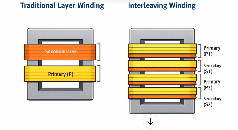
In the interleaving structure, primary and secondary windings alternate, allowing stronger magnetic coupling and better electrical performance.
What Is Layer Winding?
To better understand the difference between interleaving winding and layer winding, it is important to look at the basic structure of layer winding first. In many transformer designs, especially traditional power transformers and control transformers, layer winding is the most straightforward and widely used method. In my experience working with low-frequency transformers for industrial equipment, many stable and cost-effective designs still rely on layer winding because it provides predictable insulation spacing and a simple manufacturing process. However, the winding arrangement also influences parameters such as leakage inductance and load regulation, which is why engineers often compare it with interleaving structures when voltage stability becomes critical.
What Is Layer Winding?
Layer winding is a transformer winding technique where each winding is completed layer by layer before the next winding is added.
Typically, the primary winding is wound first across several layers. After insulation material is added, the secondary winding is wound on top of the primary layers. The structure usually looks like this:
Primary layers → insulation barrier → secondary layers
In our factory, this structure is commonly used for EI laminated transformers and encapsulated transformers, because it is easy to control insulation thickness and creepage distance between windings.
How Layer Winding Works
The basic principle of layer winding is sequential stacking of copper layers around the bobbin.
The winding process usually follows these steps:
1.Wind the first layer of the primary winding
2.Add insulation tape or insulation paper
3.Continue winding additional primary layers
4.Apply reinforced insulation between primary and secondary
5.Wind the secondary winding layers
6.Apply final insulation and finishing layers
In our production line, this process is straightforward and highly repeatable, which makes it suitable for high-volume production.
However, because the primary and secondary windings are physically separated by multiple layers of copper and insulation, the magnetic coupling between them is slightly weaker than in interleaving structures.
Main Benefit in Design
The biggest advantage of layer winding is simplicity and insulation reliability.
1. Easier Insulation Control
Layer winding allows clear separation between primary and secondary windings. This makes it easier to meet safety standards such as EN61558 or UL insulation requirements.
In my experience, when transformers require higher isolation voltage (for example 3 kV or more), layer winding simplifies the insulation design.
2. Lower Manufacturing Complexity
Because the winding is continuous and sequential, the production process is faster and easier to control.
At Unicreed, when we manufacture standard EI transformers for industrial control panels, layer winding helps maintain consistent winding tension, repeatable insulation spacing, and stable production yield.
3. Lower Interwinding Capacitance
Layer winding usually results in lower capacitive coupling between primary and secondary, which can sometimes help reduce common-mode noise in certain applications.
Typical Applications
Layer winding is widely used in many traditional transformer designs where manufacturing simplicity and insulation safety are the priority.
Common applications include:
·Industrial Control Transformers
Many 24V or 12V control power transformers used in control cabinets adopt layer winding due to their robust insulation structure.
·Linear Power Supplies
Traditional linear power supplies with rectifier and regulator circuits often use layer-wound EI transformers.
·Encapsulated Safety Transformers
Encapsulated transformers for building automation or lighting systems often use layer winding because it works well with vacuum potting processes.
·Low-Frequency Power Transformers
50/60 Hz transformers in industrial equipment frequently use this winding method because it balances performance and production efficiency.
Simple Drawing of Layer Winding Structure
Below is a simplified conceptual diagram of a layer winding transformer:
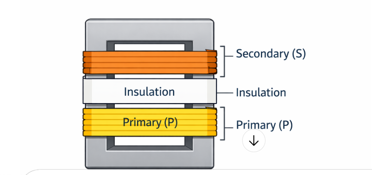
In this structure, the primary and secondary windings are placed in separate layers, with insulation between them to ensure electrical safety.
What Are The Differences Between Interleaving And Layer Winding?
After understanding how interleaving winding and layer winding work individually, the next step is to compare them directly. In transformer design, the difference between these two winding structures mainly affects magnetic coupling, leakage inductance, voltage regulation, and manufacturing complexity. In my experience working with OEM transformer projects, many engineers initially focus on core size or wire diameter, but the winding structure itself often determines whether the transformer can achieve stable output voltage under real load conditions. Below is a practical comparison based on both electrical performance and manufacturing considerations.
1. Winding Structure
The most obvious difference is how the primary and secondary windings are arranged on the bobbin.
Interleaving Winding
Primary and secondary windings are divided into sections and alternated.
Example structure:
Primary (½) → Secondary → Primary (½)
This arrangement places the windings closer together.
Layer Winding
Each winding is placed in complete layers, one on top of another.
Example structure:
Primary → Insulation → Secondary
The windings are grouped separately rather than mixed.
In our factory, we usually choose interleaving when electrical performance is critical, while layer winding is preferred for simpler production and insulation management.
2. Leakage Inductance
Leakage inductance is one of the key electrical differences.
How Interleaving Improves Voltage Stability
Comparing winding structures directly, it is important to understand why interleaving winding is often associated with better output voltage stability. In transformer design, voltage stability is closely related to how efficiently energy transfers from the primary winding to the secondary winding. In my experience working with transformer prototypes, when a design shows excessive voltage drop under load, the first parameter I usually check is leakage inductance, which is strongly influenced by the winding arrangement. This is where interleaving can make a significant difference.
1. Reduces Leakage Inductance
The most important way interleaving improves voltage stability is by reducing leakage inductance.
In a transformer, not all magnetic flux produced by the primary winding links perfectly with the secondary winding. The portion that does not couple becomes leakage flux, which contributes to leakage inductance.
When leakage inductance is high:
·Energy transfer between windings becomes less efficient
·Voltage drops more when load current increases
·Load regulation becomes worse
Interleaving reduces the distance between primary and secondary windings by alternating them in sections, which increases magnetic coupling and minimizes leakage flux.
In our factory, when we redesign transformers for better load regulation, introducing a two-section or four-section interleaving structure often significantly reduces leakage inductance.
2. Improves Magnetic Coupling
Magnetic coupling refers to how effectively the magnetic field generated in the primary winding links to the secondary winding.
In interleaving structures:
Primary and secondary windings are placed closer together and distributed across the winding window.
This leads to:
·Stronger magnetic coupling
·More efficient energy transfer
·Reduced energy loss inside the transformer
In practical transformer testing, stronger coupling directly translates to more stable output voltage when load current changes.
3. Reduces Voltage Drop Under Load
One of the most visible effects of interleaving is improved load regulation.
When the load increases, current flowing through the windings creates voltage drops due to internal impedance. Leakage inductance is a major component of this impedance.
Because interleaving lowers leakage inductance, the transformer experiences:
·Smaller voltage drop from no-load to full-load
·More consistent secondary voltage
·Better regulation performance
In my experience, when two transformers use the same core and copper size but different winding structures, the interleaved version often shows noticeably better load regulation during testing.
4. Improves Dynamic Response
Voltage stability is not only about steady-state operation. In many applications, the load changes quickly.
Examples include:
·Switching power supplies
·Industrial control systems
·Audio amplifiers
In these situations, the transformer must transfer energy quickly during load transitions.
Because interleaving improves magnetic coupling and reduces internal impedance, it allows the transformer to respond more quickly to changing current demands, which helps maintain stable output voltage.
5. Practical Engineering Perspective
In real transformer manufacturing, interleaving is often used when designers need to optimize electrical performance rather than simplify production.
In our production line, we typically consider interleaving when the design requires:
·Tight load regulation
·Low leakage inductance
·High efficiency energy transfer
However, interleaving also increases winding complexity and sometimes increases interwinding capacitance, which must be considered in high-frequency or EMI-sensitive designs.
How Layer Winding Performs in Real Designs
In real transformer designs, layer winding delivers predictable, reliable performance especially in applications where cost, insulation control, and simplicity matter more than ultra-tight voltage regulation. Because each winding is applied as one complete layer, separated by insulation, the manufacturing process is straightforward and highly repeatable. This makes layer-wound transformers easy to produce consistently, even in large volumes.
However, this structure creates a greater physical distance between primary and secondary windings. As a result, layer winding typically exhibits higher leakage inductance compared to interleaving. In real designs, this translates to slightly larger voltage drops under load and slower response to rapid load changes. For systems where the load doesn’t fluctuate dramatically, this isn’t a major issue but in fast-switching or precision applications, it can limit performance.
Despite these trade-offs, layer winding excels in designs requiring strong insulation, stable mechanical construction, and cost efficiency. It remains a dependable choice for general-purpose power supplies, household appliances, lighting, and industrial equipment where moderate voltage stability is sufficient.
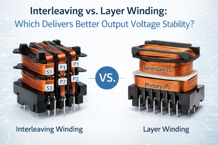
Interleaving vs. Layer Winding: Side-by-Side Comparison
To clearly see how winding structure affects transformer behavior, it helps to compare interleaving winding and layer winding side by side. In my experience working with OEM transformer designs, both structures can work well, but they prioritize different engineering goals. Interleaving focuses on electrical performance, especially coupling and voltage regulation, while layer winding often focuses on manufacturing simplicity and insulation reliability.
In our factory, when we review a new transformer project, we usually compare these two structures early in the design stage. The decision often depends on the required voltage stability, insulation requirement, load type, and production cost. The table below summarizes the most important technical differences.
Interleaving vs. Layer Winding: Side-by-Side Comparison
| Feature | Interleaving Winding | Layer Winding |
|---|---|---|
| Winding Structure | Primary and secondary are split into sections and alternately stacked (e.g., P-S-P) | Each winding is completed layer by layer before the next winding is added |
| Magnetic Coupling | Stronger coupling due to closer proximity of windings | Slightly weaker coupling due to physical separation |
| Leakage Inductance | Lower leakage inductance | Higher leakage inductance |
| Output Voltage Stability | Better load regulation and smaller voltage drop under load | Larger voltage drop when load current increases |
| Interwinding Capacitance | Higher capacitance between windings | Lower capacitance |
| EMI Behavior | May increase common-mode noise if not controlled | Often easier to manage EMI |
| Insulation Design | More complex insulation planning required | Simpler insulation structure |
| Manufacturing Complexity | More complicated winding process | Easier and faster to manufacture |
| Production Consistency | Requires tighter process control | Highly repeatable in mass production |
| Typical Applications | SMPS transformers, Flyback transformers, High-performance power designs | EI power transformers, Industrial control transformers, Linear power supplies |
At Unicreed, we usually confirm the winding structure through prototype testing, including load regulation measurement, leakage inductance testing, temperature rise testing, and Hi-pot insulation testing before moving into mass production.
Interleaving Or Layer Winding Which Delivers Better Output Voltage Stability?
To answer this question directly, interleaving winding usually delivers better output voltage stability than layer winding. However, the reason is not simply the winding style itself. The real difference comes from how the winding structure influences magnetic coupling, leakage inductance, and load regulation inside the transformer.
In my experience working with power transformer designs and production testing, voltage stability problems often appear when the winding layout creates excessive leakage inductance. That is why the choice between interleaving and layer winding becomes important when engineers require tighter voltage regulation.
Why Interleaving Usually Provides Better Voltage Stability
Stronger Magnetic Coupling
Interleaving improves magnetic coupling between the primary and secondary windings by placing them closer together.
Instead of separating the windings into large blocks, the windings are split and alternated, for example P-S-P. This arrangement allows the magnetic field generated by the primary winding to link more effectively with the secondary winding.
In my experience, transformers with stronger coupling usually maintain more stable output voltage when load current increases.
Lower Leakage Inductance
Leakage inductance is one of the main causes of voltage drop in transformers.
When the primary and secondary windings are separated by several layers of copper and insulation, part of the magnetic flux does not link both windings. This unused flux behaves like an extra inductance in the circuit.
Interleaving reduces the distance between windings and therefore reduces leakage inductance, which helps maintain the output voltage under load.
In our factory, when we evaluate transformer prototypes that show poor load regulation, improving the winding layout with partial interleaving often reduces leakage inductance and improves the results.
Better Load Regulation
Because of improved coupling and lower leakage inductance, interleaving usually results in better load regulation.
Load regulation describes the difference between:
·No-load output voltage
·Full-load output voltage
Transformers with interleaved windings normally show smaller voltage drop between these two conditions, which means better voltage stability.
This advantage becomes more obvious when the transformer output feeds a rectifier with a capacitor filter, where peak current can increase internal voltage drop.
When Layer Winding May Still Be the Better Choice
Even though interleaving often improves voltage stability, layer winding is still widely used in many transformer designs.
In my experience, layer winding is often preferred when:
·The insulation structure must remain simple and robust
·Safety spacing requirements are strict
·Production consistency and cost are important
·Voltage regulation requirements are moderate
For example, many industrial control transformers and EI power transformers use layer winding because the load is relatively stable and the insulation structure is easier to control.
Final Answer
If the goal is maximum output voltage stability, interleaving winding generally performs better than layer winding.
However, the best winding structure always depends on the complete transformer design, including load characteristics, insulation requirements, and production constraints.
Final transformer selection should always be confirmed through prototype testing in the actual operating environment.
How to Choose the Right Winding for Your Application?
To choose the right winding method, engineers should not look only at the winding structure itself. The correct choice depends on how the transformer will operate in the real application. In my experience working with OEM transformer projects, many voltage regulation or overheating problems appear because the winding structure was selected too early, before fully understanding the load behavior, insulation requirements, and space constraints.
1. Check Your Voltage Regulation Requirement
The first question I usually ask customers is how stable the output voltage needs to be under load.
If the application requires tight voltage regulation, interleaving is often the better option because it improves magnetic coupling and reduces leakage inductance.
·Typical cases where interleaving is preferred include:
·Switching power supplies
·Low-voltage high-current outputs
·Circuits sensitive to voltage variation
In my experience, when the load current changes quickly or reaches a high peak value, interleaving helps maintain more stable output voltage.
Layer winding can still work well when the regulation requirement is moderate. Many industrial control transformers operate reliably with this structure.
2. Understand the Type of Load
The type of load connected to the transformer can strongly influence the winding choice.
Two common cases are:
Resistive or AC loads
These loads draw relatively smooth current. In these situations, layer winding usually performs adequately.
Rectifier with capacitor filter
This load type draws high peak currents. The effective current inside the transformer can be significantly higher than the average output current.
In our factory testing, transformers supplying rectifier loads often show larger voltage drop when the leakage inductance is high. Interleaving can help reduce this problem.
3. Consider Safety and Insulation Requirements
Another key factor is the required isolation voltage and safety standard.
Layer winding usually makes insulation design easier because the primary and secondary windings are clearly separated by insulation layers.
When we build transformers that must pass high isolation tests such as 3 kV or higher Hi-pot, layer winding can simplify the insulation structure and help maintain required creepage distances.
Interleaving is still possible, but the insulation design becomes more complex and must be carefully verified.
4. Evaluate EMI and Parasitic Capacitance
Interleaving improves coupling but it can also increase interwinding capacitance.
Higher capacitance can transfer more high-frequency noise between primary and secondary. In switching power supplies this may influence EMI performance.
In some designs we use partial interleaving instead of full interleaving. This approach balances coupling improvement while keeping capacitance under control.
5. Consider Manufacturing and Cost
From a manufacturing perspective, layer winding is usually simpler.
The winding process is continuous and easy to repeat on automatic winding machines. This helps maintain consistent quality in large production runs.
Interleaving requires splitting windings into sections and carefully controlling insulation placement, which increases production complexity.
At Unicreed, when we evaluate transformer designs for OEM customers, we always consider whether the performance benefit of interleaving justifies the additional manufacturing complexity.
Conclusion:
Choosing between interleaving winding and layer winding is not only a structural decision. It directly affects output voltage stability, load regulation, and overall power supply performance. As we have seen, interleaving winding typically provides tighter magnetic coupling and lower leakage inductance, which helps maintain a more stable output voltage, especially in demanding applications such as industrial control systems, smart meters, security equipment, and medical devices. Layer winding, on the other hand, remains a practical solution for simpler or cost-sensitive designs where extreme voltage stability is not required.
From my experience working with power supply designers, the best transformer solution always depends on your specific application, electrical requirements, and reliability expectations.
At Unicreed, we specialize in designing and manufacturing high-performance custom transformers tailored for your equipment. If you are looking to improve output voltage stability, system reliability, or transformer efficiency, our engineering team is ready to help.
Related Transformer Articles:
- From No-Load to Full-Load: How Transformer Winding Methods Affect Voltage Regulation
- How Harness Length, Wire Gauge, and Twisting Affect Transformer Output Voltage?
- How To Choosing the Right Dual Primary or Secondary Windings for Your Transformer Design?
- 5 Ways Unicreed Customizes Transformers for Your System
- How We Wind Copper Wire for High-Efficiency Toroidal Transformers?
