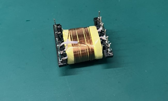
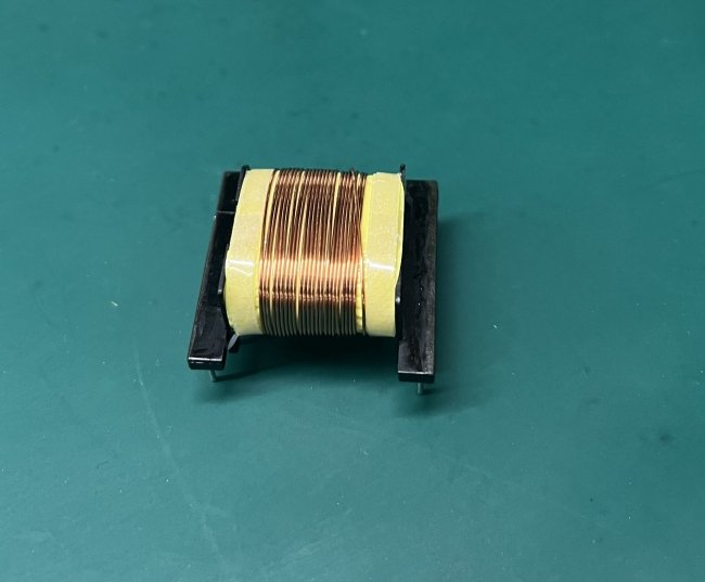
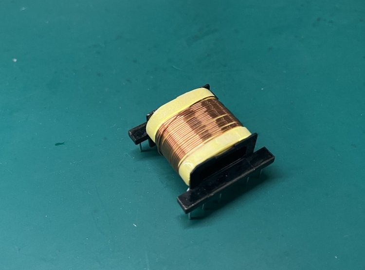
In modern technology, high-frequency transformers play a crucial role in power conversion, signal processing, and electronic devices. It is essential that these transformers are used to convert electrical energy from one voltage level to another, which allows for efficient power transfer and control.
One important factor in the design and performance of high-frequency transformers is the wire turn count. The number of turns of wire around the transformer’s core determines its magnetic field strength and affects its electrical characteristics, including impedance, inductance, and efficiency. Choosing the optimal wire turn count is critical to ensuring that a transformer operates effectively and safely in its intended application.
This article examines the factors that determine the best wire turn count for a high-frequency transformer. It will be discussed in detail how frequency of operation, core material, magnetic flux density, voltage and current requirements, and desired power output impact efficiency. Also covered will be the calculation of wire turn counts, practical considerations, and the importance of selecting the correct wire turn count. This article will provide valuable insight into optimizing the performance of your high-frequency transformer, regardless of whether you are an engineer, researcher, or enthusiast.
What is wire turn count, and why is it important in designing high-frequency transformers?
Wire turn count refers to the number of turns of wire that are wound around the core of a transformer. It is an important factor in the design of high-frequency transformers because the number of turns affects the transformer’s impedance, inductance, and coupling coefficient, which in turn affect its performance.
In general, a higher number of turns will result in a higher inductance and impedance, while a lower number of turns will result in a lower inductance and impedance. The coupling coefficient between the primary and secondary windings is also affected by the number of turns, with a higher number of turns resulting in a higher coupling coefficient.
In high-frequency transformers, the wire turn count is particularly important because the transformer must operate efficiently at high frequencies. This means that the transformer must have low resistance and low capacitance, and the wire used to wind the transformer must be carefully selected to minimize losses and reduce parasitic capacitance. The wire turn count must also be optimized to ensure that the transformer is operating within its intended frequency range and with the desired performance characteristics.
What is the definition of the number of turns and its relationship to transformer performance?
The number of turns refers to the number of times a wire is wrapped around the core of a transformer. The number of turns is an important factor in determining the performance of a transformer because it affects the transformer’s voltage ratio, impedance, inductance, and coupling coefficient.
The voltage ratio of a transformer is directly proportional to the turns ratio. The turns ratio is defined as the ratio of the number of turns on the secondary winding to the number of turns on the primary winding. For example, if a transformer had twice as many turns on its secondary winding as its primary winding, its turns ratio would be 2:1. The turns ratio determines how much the voltage is stepped up or down from the input to the output of the transformer.
The number of turns also affects the impedance and inductance of the transformer. Inductance is proportional to the square of the number of turns, so increasing the number of turns increases the inductance. Impedance, which is the total opposition to current flow in a circuit, is proportional to the number of turns. This means that increasing the number of turns also increases the transformer’s impedance.
Finally, the number of turns affects the coupling coefficient, which is a measure of the extent to which the magnetic field of the primary winding is transferred to the secondary winding. The coupling coefficient is directly proportional to the square root of the product of the inductances of the primary and secondary windings, and it is also affected by the number of turns in each winding.
What are some practical considerations when calculating the wire turn count for a high-frequency transformer?
Calculating the wire turn count for a high-frequency transformer involves several practical considerations to ensure that the transformer operates efficiently and with the desired performance characteristics. Here are some practical considerations when calculating the wire turn count for a high-frequency transformer:
- Core material: The type of core material used in the transformer affects the wire turn count. Ferrite cores, for example, require more turns of wire than iron or laminated steel cores. The choice of core material also affects the transformer’s saturation point and frequency range.
- Operating frequency: The operating frequency is a critical factor in determining the wire turn count. The higher the frequency, the fewer turns are needed to achieve the desired inductance. However, at higher frequencies, the skin effect becomes significant, and the wire’s diameter must be considered to minimize resistance and parasitic capacitance.
- Input and output voltage: The input and output voltage of the transformer determine the turns ratio, which is the ratio of the number of turns on the secondary winding to the number of turns on the primary winding. The turns ratio affects the voltage gain or loss of the transformer.
- Maximum current: The maximum current that the transformer must handle determines the wire gauge needed. The wire gauge affects the resistance and the power loss of the transformer.
- Parasitic capacitance: The number of turns, wire diameter, and spacing between the turns all contribute to the transformer’s parasitic capacitance, which can significantly affect the transformer’s performance at high frequencies.
- Thermal considerations: The wire gauge and number of turns affect the transformer’s power handling capability and temperature rise. If the transformer is designed to operate at high power levels, thermal management must be considered.

What is the mathematical formula for calculating the number of wire turns? And an example calculation using a hypothetical transformer?
The formula for calculating the number of wire turns in a transformer depends on the desired inductance, the core material, and the winding configuration. Here is an example calculation using a hypothetical transformer:
Suppose we want to design a transformer with a desired inductance of 10 mH, using a core material with a permeability of 2000 henries/meter. The wire we plan to use has a diameter of 0.5 mm, and we plan to wind the transformer in a single layer on a toroidal core with an average diameter of 10 cm.
Using the formula for a toroidal coil with a single layer of wire, the number of turns N is given by:
N = (AL Bmax) / (0.4 pi * D)
Where AL is the inductance factor of the core material, Bmax is the maximum flux density in teslas, D is the average diameter of the core in meters, and pi is pi (3.14159…).
We can assume a maximum flux density of 0.3 teslas for our core material. The inductance factor AL depends on the core geometry and is typically given by the core manufacturer. Let’s assume a value of 1000 nH/turn^2 for our core.
Substituting these values, we get:
N = (1000 nH/turn^2 0.3 T) / (0.4 pi * 0.1 m) = 238 turns
So we need to wind our transformer with 238 turns of wire to achieve a desired inductance of 10 mH.
Note that this is just an example calculation, and the actual number of turns may differ depending on the specific design requirements of the transformer.
What are the precautions when determining the appropriate number of wire turns?
When determining the appropriate number of wire turns for a transformer, there are several precautions to consider:
- Core saturation: The number of turns should be chosen such that the maximum flux density in the core does not exceed its saturation limit. Exceeding the saturation limit can lead to a distorted output waveform, overheating of the transformer, and ultimately, transformer failure.
- Voltage and current ratings: The number of turns should be chosen such that the transformer can handle the voltage and current ratings for its intended application. Exceeding these ratings can lead to breakdown of the insulation between the windings, arcing, and other safety hazards.
- Winding resistance: The number of turns should be chosen such that the winding resistance is within acceptable limits for the intended application. Excessive winding resistance can lead to power losses, reduced efficiency, and overheating of the transformer.
- Temperature rise: The number of turns should be chosen such that the temperature rise of the transformer does not exceed the recommended limits for the insulation and core materials. Excessive temperature rises can lead to insulation breakdown, reduced efficiency, and other safety hazards.
- Frequency range: The number of turns should be chosen based on the frequency range of the intended application. At high frequencies, the skin effect and proximity effect can increase the effective resistance of the winding and reduce the efficiency of the transformer.
- Manufacturing constraints: The number of turns should be chosen with manufacturing constraints in mind, such as wire size, winding space, and winding complexity.
Can the magnetic flux density impact the wire turn count in high-frequency transformers?
Yes, the magnetic flux density can impact the wire turn count in high-frequency transformers.
In high-frequency transformers, the frequency of the AC current is high, which means that the magnetic flux in the transformer core changes rapidly. The magnetic flux density is directly proportional to the number of turns of wire in the transformer coil, as stated by Faraday’s law of electromagnetic induction. Therefore, increasing the magnetic flux density requires a corresponding increase in the number of turns of wire in the transformer coil.
However, there are limits to how many turns can be added to the transformer coil. As the number of turns increases, the resistance of the wire also increases, leading to increased losses due to heating. Additionally, the increased number of turns can lead to increased capacitance between the turns, which can affect the transformer’s performance.
How do the voltage and current requirements of a high-frequency transformer affect the wire turn count?
The voltage and current requirements of a high-frequency transformer can affect the wire turn count in several ways.
Firstly, the voltage requirement determines the insulation requirements for the wire used in the transformer. Higher voltages require higher levels of insulation, which can increase the size of the wire and reduce the number of turns that can fit in the available space.
Secondly, the current requirement determines the cross-sectional area of the wire required to handle the current without overheating. Higher currents require larger wires, which can again reduce the number of turns that can fit in the available space.
Thirdly, the voltage and current requirements together determine the power rating of the transformer. The power rating is the product of the voltage, current, and efficiency of the transformer. To achieve a given power rating, the transformer must have a certain number of turns of wire to provide the required magnetic flux density.
Therefore, in designing a high-frequency transformer, the designer must take into account the voltage and current requirements to determine the appropriate wire size and insulation, and balance these requirements against the number of turns needed to achieve the desired magnetic flux density for the required power rating.

Is there a relationship between the desired power output of a high-frequency transformer and the wire turn count?
Yes, there is a relationship between the desired power output of a high-frequency transformer and the wire turn count.
The power output of a transformer is proportional to the product of the input voltage, the output current, and the efficiency of the transformer. The magnetic flux density in the transformer core is directly proportional to the number of turns of wire in the transformer coil. This is stated by Faraday’s law of electromagnetic induction. Therefore, to achieve a desired power output, the designer must select a wire turn count that will provide the required magnetic flux density for the transformer’s core.
As the power output of the transformer increases, the current flowing through the transformer also increases. This current produces heat in the wire due to its resistance, and the heat must be dissipated to prevent damage to the wire and the transformer as a whole. Therefore, the wire size must also be selected to handle the required current without overheating.
How do you optimize efficiency in a high-frequency transformer through wire turn count selection?
Optimizing efficiency in a high-frequency transformer through wire turn count selection involves selecting a wire turn count that will provide the required magnetic flux density while minimizing losses due to resistance and leakage.
The wire turn count determines the magnetic flux density in the transformer core, which in turn affects the voltage and current levels in the transformer. Increasing the number of turns of wire in the transformer coil can increase the magnetic flux density. However, this can also increase the resistance of the wire and the leakage of the magnetic field, leading to increased losses.
It is essential for the designer to balance the desired magnetic flux density with wire resistance and leakage in order to optimize efficiency. This can involve selecting a wire size and insulation that can handle the required current without excessive heating. In addition, choosing a core material and design that minimize magnetic field leakage.
Additionally, the designer may choose to use advanced winding techniques, such as interleaved winding or bifilar winding, to reduce leakage and increase coupling between the windings.
Simulation and modeling tools can also be used to optimize the wire turn count and other design parameters for maximum efficiency. By modeling the behavior of the transformer under different operating conditions, the designer can identify the optimal wire turn count and other design factors. This will provide the desired performance while minimizing losses.
Can using an incorrect wire turn count in a high-frequency transformer lead to performance issues?
Yes, using an incorrect wire turn count in a high-frequency transformer can lead to performance issues.
If the wire turn count is too low, the magnetic flux density in the transformer core may not be sufficient to achieve the required voltage or power output. This can lead to decreased efficiency and performance, as well as increased losses due to resistance and leakage.
Conversely, if the wire turn count is too high, the resistance of the wire may increase, leading to increased losses due to heating. Additionally, the increased capacitance between the turns can affect the transformer’s performance and introduce additional losses.
Using an incorrect wire turn count can also affect the frequency response of the transformer. High-frequency transformers must be designed to minimize the effect of parasitic capacitance and inductance, and an incorrect wire turn count can result in a transformer that is poorly matched to the operating frequency.
In some cases, using an incorrect wire turn count can also lead to reliability issues. Overheating due to high resistance can lead to insulation breakdown and wire failure, while excessive leakage can result in electromagnetic interference (EMI) or interference with other circuits.
Therefore, it is important to carefully select the appropriate wire turn count for a high-frequency transformer to ensure optimal performance, efficiency, and reliability. This requires consideration of the desired power output, voltage and current requirements, frequency response, and other design factors. Simulation and modeling tools can also be used to evaluate the performance of the transformer under different operating conditions and optimize the wire turn count and other design parameters.
Choosing the correct wire turn count is crucial for achieving optimal performance, efficiency, and reliability in high-frequency transformers. The wire turn count determines the magnetic flux density in the transformer core, which in turn affects the voltage and current levels and the power output of the transformer. An incorrect wire turn count can result in decreased efficiency and performance, increased losses, and reliability issues such as wire failure or EMI.
In conclusion, selecting the correct wire turn count for a high-frequency transformer requires careful consideration of the desired power output, voltage and current requirements, frequency response, and other design factors. With advances in simulation and modeling tools, transformer designers have more opportunities to optimize their designs for maximum efficiency and performance. In the future, we may see further developments in materials, winding techniques, and other aspects of transformer technology that will enable even more efficient and reliable high-frequency transformers. As a result, selecting the correct wire turn count will continue to play a vital role in achieving optimal transformer performance.


