Buying a custom encapsulated PCB transformer is not simply about providing the input and output voltage. The final design is also affected by rated VA, load type, ambient temperature, PCB dimensions, insulation requirements, protection method, and applicable safety standards.
In our factory, we often receive RFQs with only basic information such as “230VAC input, 12V output, 500mA.” In many cases, this is not enough to select the correct transformer, especially when the secondary output is connected to a bridge rectifier and smoothing capacitor.
For OEM projects, a complete specification at the beginning can significantly reduce design changes, shorten sample validation, and avoid problems such as excessive temperature rise, poor voltage regulation, or incorrect PCB dimensions.
1. Define the Electrical Specifications Before Requesting a Quote
The first step in developing a custom encapsulated PCB transformer is to clearly define the electrical requirements. Incomplete specifications are one of the most common causes of repeated design changes during the sampling stage.
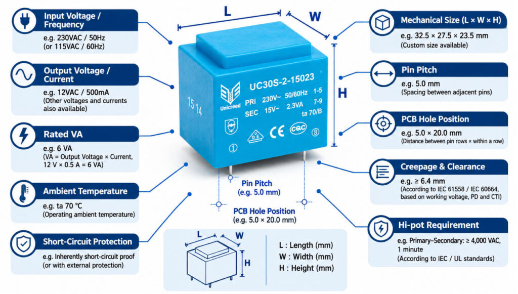
At minimum, the manufacturer should know:
- Primary voltage – such as 115VAC, 230VAC, or dual 115/230VAC input
- Operating frequency – typically 50Hz or 60Hz
- Secondary voltage – required AC output voltage under rated load
- Secondary current – maximum continuous load current
- Number of secondary windings – single, dual, or multiple outputs
- Required VA rating
- Load type – AC load or rectifier/capacitor load
- Operating mode – continuous or intermittent operation
In our factory, one of the most common mistakes we see is selecting transformer power only from the required output voltage and current without considering the actual load circuit.
For a simple AC resistive load, VA calculation is relatively straightforward. However, if the transformer supplies a bridge rectifier and smoothing capacitor, the winding current becomes more pulsed and the required transformer VA may be significantly higher than the simple DC voltage × current calculation.
2. Do Not Calculate Transformer VA Only from DC Voltage × Current
One of the most common sizing mistakes in encapsulated PCB transformer projects is calculating transformer power only from the required DC output voltage and current.
For a simple AC resistive load, transformer power can usually be estimated from:
VA = Secondary Voltage × Secondary Current
However, when the transformer secondary is connected to a bridge rectifier and smoothing capacitor, the situation is different. The capacitor charges only during part of each AC cycle, creating short and relatively high current pulses in the secondary winding.
As a result, the transformer winding RMS current can be much higher than the DC load current. This increases winding loss, voltage drop, and temperature rise.
For example, if a customer requires 12VDC at 500mA, simply calculating:
12V × 0.5A = 6W
does not mean that a 6VA transformer is automatically sufficient.
In our factory, we often see excessive temperature rise or poor output voltage regulation when the transformer VA is selected only from the DC output power. For rectifier and capacitor loads, the transformer should be evaluated together with the rectifier circuit, filter capacitor, required DC voltage, load current, and acceptable temperature rise.
3. Confirm PCB Footprint, Pin Layout and Maximum Transformer Height
For encapsulated PCB transformers, electrical performance is only part of the design. The transformer must also fit the customer’s PCB and mechanical enclosure correctly.
Before starting a custom design, we normally confirm the key mechanical dimensions, including:
- Transformer length, width and maximum height
- Pin pitch and pin position
- Pin diameter
- PCB hole size
- Primary and secondary pin arrangement
- Available spacing around the transformer
In our factory, we often see projects where the electrical specification is clear, but the PCB footprint is not fully confirmed. Even a small change in transformer height or pin spacing may require a different bobbin, lamination stack, or winding arrangement.
For OEM projects, we recommend providing the PCB drawing, 3D space limitation, or existing transformer dimensions whenever possible. This allows the manufacturer to evaluate both the electrical design and mechanical compatibility before producing samples.
4. Check Ambient Temperature, Temperature Rise and Insulation Class
Thermal performance is another critical factor when selecting a custom encapsulated PCB transformer. A transformer that works correctly at room temperature may not perform the same way inside a closed control cabinet or other high-temperature environment.
Three parameters should be considered separately:
- Ambient temperature (Ta) – the temperature around the transformer during operation
- Temperature rise – the increase in winding temperature caused by transformer losses
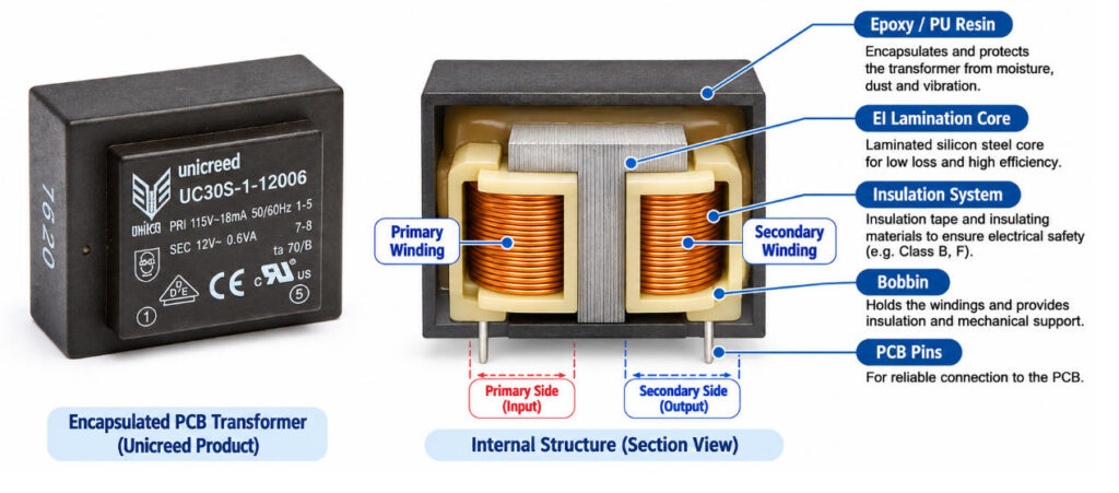
- Insulation class – the thermal rating of the insulation system, such as Class B (130°C)
In our factory, we often see customers specify only the room temperature, while the actual temperature around the transformer inside the equipment can be much higher after the system reaches thermal stability.
For example, if the ambient temperature around the transformer is already high, the allowable temperature rise becomes more limited. This can affect the required core size, winding design, copper loss, and rated VA.
When we build transformers for industrial control cabinets, the first thing we check is not only the nominal power, but also the actual ambient temperature and ventilation conditions inside the equipment.
5. Confirm the Insulation Structure and Safety Requirements
For encapsulated PCB transformers, insulation design directly affects product safety, PCB layout, transformer size, and compliance requirements. Before starting the design, the manufacturer should understand the required insulation level between the primary and secondary windings.
Typical considerations include:
- Basic insulation or reinforced insulation
- Creepage distance
- Clearance distance
- Primary-to-secondary dielectric strength
- Insulation resistance
- Target market and applicable safety requirements
In our factory, we often see projects where the electrical specification is complete, but the insulation requirement is not clearly defined. This can lead to redesign later because a transformer for a general industrial application may require a different insulation structure from one used in Class II equipment or other safety-critical applications.
The required creepage and clearance distances depend on several factors, including working voltage, insulation material, pollution degree, and the applicable safety standard. For this reason, engineers should not rely only on a Hi-pot value when evaluating transformer safety.
6. Determine the Required Short-Circuit Protection
Short-circuit protection should be confirmed during the transformer design stage, especially for encapsulated PCB transformers used in industrial control, appliances, and other safety-related applications.
Common protection methods include:
- Inherently short-circuit proof design
- Internal thermal fuse
- PTC protection
- External primary or secondary fuse
Each method has different effects on transformer construction, temperature behavior, cost, and safety evaluation.
In our factory, we normally confirm the protection method before finalizing the winding design. For example, adding an internal thermal fuse may require changes to the winding structure and assembly process, while an external fuse allows more flexibility but must be correctly selected in the customer’s circuit.
For some low-power transformers, an inherently short-circuit proof design may be possible. For higher-power units, external protection or internal thermal protection is often required depending on the applicable safety standard and end application.
7. What Should You Test on Transformer Samples?
Sample validation is not only about checking whether the transformer can power the circuit. Before approving a custom encapsulated PCB transformer for mass production, the sample should be tested under the actual application conditions.
In our factory, we normally recommend checking the following items:
| Test Item | Why It Matters |
|---|---|
| No-load secondary voltage | Checks voltage regulation and winding design |
| Rated-load voltage | Confirms output performance under actual load |
| No-load current | Helps evaluate magnetic design and core performance |
| No-load loss | Important for standby power and efficiency |
| Temperature rise | Verifies thermal margin under continuous operation |
| Hi-pot test | Confirms primary-to-secondary insulation strength |
| Insulation resistance | Checks insulation integrity |
| Dimensions and pin position | Confirms PCB and enclosure compatibility |
| Noise and vibration | Helps identify lamination or assembly issues |
In my experience, one of the most important steps is testing the transformer with the real load circuit, especially when the secondary is connected to a bridge rectifier and smoothing capacitor. A transformer that performs well with a resistive load may show different voltage drop and temperature rise in the actual power supply.
8. What Quality Controls Should an Encapsulated Transformer Factory Perform?
Quality control for encapsulated PCB transformers should not rely only on final inspection. Key electrical and safety parameters need to be controlled throughout the production process.
At Unicreed, our production process includes multiple inspection points, including:
- 100% semi-finished product electrical testing
- 100% Hi-pot testing
- 100% finished-product electrical testing
- 100% appearance inspection
- Final OQC sampling inspection
These checks help identify winding errors, insulation problems, incorrect output voltage, poor soldering, resin defects, and dimensional issues before shipment.
In our production line, we pay particular attention to electrical consistency because even small variations in winding turns, wire connection, or assembly can affect no-load voltage, load regulation, temperature rise, and insulation performance.
For OEM customers, we also recommend confirming whether the manufacturer can provide:
- Product drawings
- Electrical specifications
- Test reports
- Batch traceability
- Material declarations when required

How to Evaluate an Encapsulated PCB Transformer Manufacturer
Choosing the right manufacturer is not only about price. For custom encapsulated PCB transformers, the supplier should have both engineering capability and stable production control.
When evaluating a transformer manufacturer, we recommend checking the following areas:
- Engineering support – Can the supplier understand electrical specifications, PCB drawings, thermal requirements, insulation structure, and safety requirements?
- Customization capability – Can they adjust voltage, VA, pin layout, dimensions, winding structure, and protection method according to your application?
- Production process – Does the factory control key processes such as winding, soldering, varnishing, encapsulation, assembly, and electrical testing?
- Quality control – Are semi-finished products, Hi-pot, finished electrical parameters, appearance, and OQC properly inspected?
- Traceability – Can the manufacturer trace production batches, materials, and test records?
- Technical documentation – Can they provide drawings, specifications, test reports, and material declarations when required?
- Mass-production consistency – Can the supplier maintain the same electrical and mechanical performance from samples to large-volume production?
In our factory, we often see that the real difference between suppliers becomes clear after the sample stage. Producing one acceptable sample is not difficult; maintaining consistent voltage, temperature rise, insulation performance, dimensions, and appearance across thousands of units is much more important.
For OEM projects, we usually follow the sequence of requirement review → drawing confirmation → sample validation → pilot production → mass production. This process helps reduce design changes and quality risks before full-volume production.
Conclusion
Sourcing a custom encapsulated PCB transformer is not only about comparing price and delivery time. A reliable design starts with complete electrical specifications, correct VA selection, suitable PCB dimensions, thermal evaluation, insulation requirements, and the right protection method.
At Unicreed, we support OEM customers from requirement review and transformer design to sample validation and mass production. If you are developing a custom encapsulated PCB transformer, please provide your input voltage, output voltage/current, load type, PCB dimensions, ambient temperature, safety requirements, and estimated quantity for engineering evaluation.
Related Transformer Articles:
- PCB Mount Encapsulated Transformer Option
- How to Choose the Right EE20 Transformer for Your Needs?
- From No-Load to Full-Load: How Transformer Winding Methods Affect Voltage Regulation
- Why Transformer Windings Should Avoid Crossing?
- 8 Design Methods to Meet Safety Requirements in High-Frequency Transformers