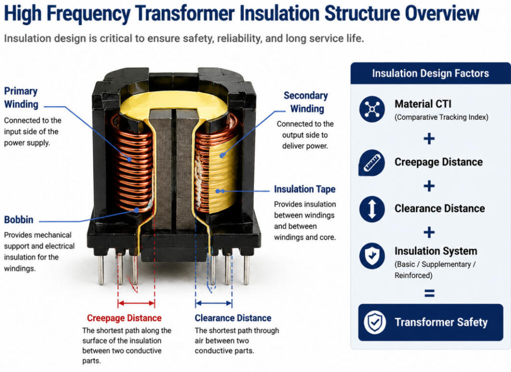
In high frequency transformers, insulation design is just as important as electrical performance. While engineers usually focus on parameters such as power rating, efficiency, temperature rise, and switching frequency, insulation reliability is also a critical factor affecting product safety and lifetime.
One important parameter used to evaluate insulation materials is CTI (Comparative Tracking Index). CTI indicates the resistance of an insulating material to electrical tracking under moisture and contamination conditions, and it directly affects the selection of insulation materials and creepage distance design.
In our factory, we often consider CTI when selecting transformer bobbins, insulation materials, and safety structures for customized high frequency transformers. Understanding CTI helps engineers make better decisions on insulation systems, especially for applications requiring higher safety standards and long-term reliability.
In this blog, we will explain what CTI means, why it matters in high frequency transformers, and how it influences insulation design and material selection.
What Is CTI (Comparative Tracking Index)?
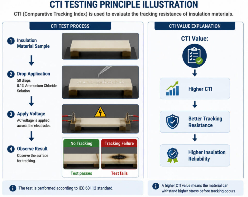
CTI (Comparative Tracking Index) is a measurement of the electrical tracking resistance of an insulation material. It indicates the maximum voltage that an insulating material surface can withstand without forming a conductive tracking path under standardized testing conditions.
In the CTI test, the insulation material is exposed to 50 drops of 0.1% ammonium chloride solution, and the highest voltage without surface tracking failure is recorded as the CTI value.
For high frequency transformers, CTI is an important insulation design parameter because it affects the required creepage distance between conductive parts. A higher CTI value means the material has better resistance against leakage current and surface tracking, allowing a shorter creepage distance under the same working voltage.
In simple terms:
Higher CTI = Better tracking resistance
Higher CTI = Shorter required creepage distance
Higher CTI materials are more suitable for high voltage and safety-critical applications
In our factory, CTI is one of the key factors we consider when selecting transformer bobbins and insulation materials. Proper CTI selection helps ensure that customized high frequency transformers meet safety requirements while maintaining a compact design.
According to IEC insulation classification, insulation materials are generally divided into four groups based on CTI:
| Material Group | CTI Value |
|---|---|
| Group I | CTI ≥ 600V |
| Group II | 400V ≤ CTI < 600V |
| Group IIIa | 175V ≤ CTI < 400V |
| Group IIIb | 100V ≤ CTI < 175V |
For commonly used transformer insulation materials, materials such as PM9630 and PM9820 are typically classified as Group III materials, with CTI values between 175V and 250V. Some engineering plastics such as WH9100 and WH8100 can achieve Group I classification with CTI ≥ 600V.
| Material | Certification | CTI Group | CTI Value | Supplier |
|---|---|---|---|---|
| PM9630 | E41429 | CTI = 3 | 175V ≤ CTI < 250V | Sumitomo |
| PM9820 | E41429 | CTI = 3 | 175V ≤ CTI < 250V | Sumitomo |
| WH9100 | E150608 | CTI = 0 | CTI ≥ 600V | Huayu New Material |
| WH8100 | E150608 | CTI = 0 | CTI ≥ 600V | Huayu New Material |
How CTI, Pollution Degree and Creepage Distance Affect Transformer Safety Design
CTI alone does not determine the creepage distance requirement of a transformer. In practical transformer design, creepage distance is also affected by the surrounding environment, especially the level of pollution.
According to insulation coordination principles, environments are generally divided into four pollution degrees:
| Pollution Degree | Description | Typical Application |
|---|---|---|
| PD1 | No pollution or only dry, non-conductive pollution | Clean laboratory environment |
| PD2 | Normal pollution, occasional condensation possible | General industrial equipment |
| PD3 | Heavy pollution with frequent condensation | Outdoor, dusty or salt-mist environments |
| PD4 | Severe conductive pollution | Chemical environments with conductive dust |
Based on the working voltage, pollution degree, and CTI classification of the insulation material, engineers can determine the required minimum creepage distance.
For example, in a typical 220VAC input switching power supply, the corresponding DC voltage is approximately 311VDC. According to insulation distance requirements:
Working voltage: 320VDC
Pollution degree: PD2
Material group: CTI Group III
The required minimum creepage distance for basic insulation is 3.2mm.
For reinforced insulation between the primary and secondary side, the requirement is generally twice the basic insulation distance, resulting in 6.4mm creepage distance.
This is why many safety transformer designs commonly require a 6.4mm minimum creepage distance between primary and secondary circuits.
In our production experience, achieving the required creepage distance is not only a matter of selecting the right material. Transformer structure, bobbin design, insulation tape thickness, margin tape, and winding arrangement must all work together to meet safety requirements.
Why CTI Matters in High Frequency Transformer Insulation Design
In high frequency transformers, insulation design is as important as electrical performance. As power supplies continue to move toward higher power density and smaller size, the available insulation space inside transformers becomes more limited, making material selection increasingly important.
CTI is a key parameter that helps engineers evaluate the resistance of insulation materials against surface tracking. A material with insufficient CTI performance may develop conductive paths on its surface under the combined effects of voltage stress, moisture, and contamination, which can eventually lead to insulation failure.
In high frequency transformer applications, CTI directly affects several important design factors, including:
- Insulation material selection
- Creepage distance requirements
- Primary-to-secondary safety spacing
- Long-term reliability under different operating environments
For example, two insulation materials may have similar mechanical strength, but the material with a higher CTI value can provide better resistance against leakage tracking and may allow a more compact insulation structure under the same voltage requirements.
In our factory, we often see that transformer safety is not determined by a single parameter such as dielectric strength (Hi-pot). A reliable insulation system requires a combination of CTI performance, creepage distance, clearance, insulation structure, and actual application conditions.
For customized high frequency transformers, CTI evaluation is therefore an important step during the early design stage. Choosing the right insulation material helps balance safety requirements, transformer size, and manufacturing feasibility.
How CTI Affects Creepage Distance Requirements
How CTI Affects Creepage Distance Requirements
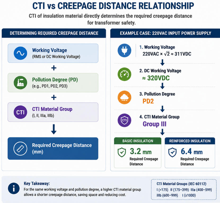
CTI is closely related to creepage distance design in high frequency transformers. However, CTI does not directly define the required distance. Instead, it is one of the key factors used together with working voltage, insulation type, and pollution degree to determine the minimum creepage distance required for safe operation.
Creepage distance is the shortest distance along the surface of an insulating material between two conductive parts. It is designed to prevent surface leakage current and electrical tracking under normal operating conditions.
A higher CTI material has better resistance against surface tracking. Therefore, under the same working voltage and pollution condition, a higher CTI material can usually achieve the required insulation performance with a shorter creepage distance. This is especially important for high frequency transformers, where engineers often need to balance safety requirements with compact size and high power density.
In transformer design, the creepage distance requirement is mainly determined by three factors:
- Working voltage – Higher voltage requires a longer creepage distance.
- Pollution degree – A more contaminated environment increases the risk of surface leakage.
- CTI value of insulation material – Higher CTI materials provide better tracking resistance.
For example, in a typical 220VAC input switching power supply, the peak DC voltage after rectification is approximately:
220VAC × √2 ≈ 311VDC
According to insulation coordination requirements:
Working voltage: 320VDC
Pollution degree: PD2
Insulation material: CTI Group III
The required minimum creepage distance for basic insulation is 3.2mm.
For reinforced insulation, which is commonly required between the primary and secondary sides of safety transformers, the creepage distance is generally doubled:
3.2mm × 2 = 6.4mm
This is why many input transformers and switching power supply transformers commonly require a minimum 6.4mm creepage distance between primary and secondary circuits.
In our factory, creepage distance is one of the key items we review during transformer design verification. We consider not only CTI values, but also bobbin structure, insulation tape system, winding arrangement, and the actual operating environment to ensure the final transformer design meets safety requirements.
How Transformer Manufacturers Select CTI Materials in Real Production
In real transformer production, CTI is only one factor in bobbin material selection. Engineers also need to consider working voltage, required creepage distance, pollution degree, insulation class, temperature resistance, mechanical strength, processability, and cost.
For example, commonly used phenolic materials such as PM9630 and PM9820 fall into Material Group IIIa, while materials such as WH9100 and WH8100 can reach CTI ≥ 600V, corresponding to Material Group I. When the available creepage distance is limited or the application requires higher insulation performance, a higher-CTI material can provide more design flexibility.
However, manufacturers do not simply choose the highest CTI available. A higher-CTI material may also come with higher material cost or different molding and mechanical characteristics. In practice, the goal is to select a material that meets the required safety standard and creepage distance while keeping the transformer reliable and cost-effective.
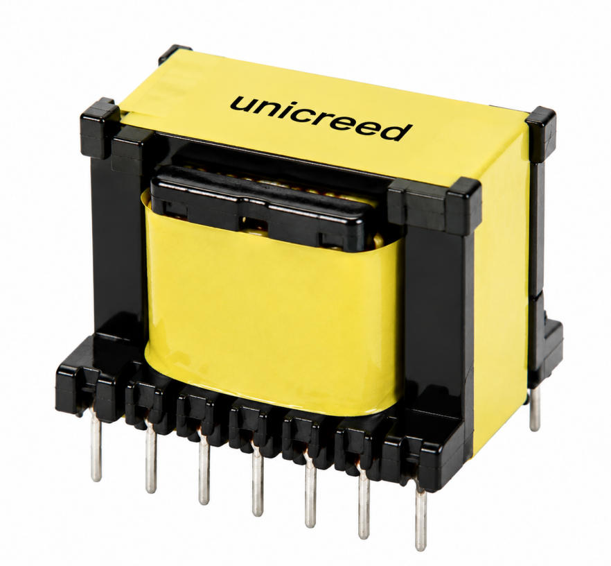
At Unicreed, we normally evaluate the bobbin material together with the transformer structure, operating environment, and end-product safety requirements before confirming the final design.
Conclusion
CTI is not only a material parameter, but also an important part of transformer insulation and safety design. A suitable CTI material should always be selected together with the working voltage, operating environment, insulation system, and required creepage distance.
Before mass production, prototype testing is also essential to verify that the complete transformer design meets the required electrical and reliability performance.
If you are developing a high-frequency transformer and are unsure which bobbin material or CTI level is suitable for your application, contact Unicreed. Our engineering team can support you with material selection, insulation design, prototyping, and customized transformer solutions.
Related Transformer Articles:
- 8 Design Methods to Meet Safety Requirements in High-Frequency Transformers
- What Materials Are The High Frequency Transformers Made Of ?
- How to Improve HI-POT Performance Poor in High-Frequency Transformers?
- Key Considerations for Impregnation in High-Frequency Transformers
- How Should The Lead Wire Be Positioned When Design An SMPS Transformer?