Have you ever measured a transformer output at 24V on the bench, but only 21.8V at the actual load? Many engineers immediately suspect the transformer design, the turns ratio, or even manufacturing quality. I have seen this situation countless times. In our factory, customers often return samples claiming “low output voltage,” only to discover that the real issue is wiring layout.
The real problem is not the transformer itself. It is the resistance hidden in long cables, thin PCB traces, poor grounding paths, or incorrect secondary connections. When current flows, every milliohm matters. Voltage drop increases, regulation worsens, and under DC rectified loads, the situation becomes even more critical.
In this blog, I will explain from real production and field experience how wiring layout directly affects transformer output voltage, and how you can prevent costly misjudgments in your next design.
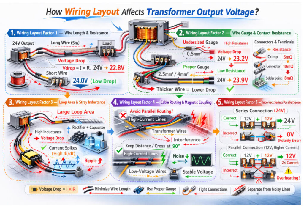
In my experience, most “transformer voltage problems” are not inside the transformer at all, but in the way it is wired into the real system. On the test bench, with short, thick leads and clean connections, the output looks perfect. But once the transformer is installed in a cabinet, running through long harnesses, terminal blocks and crowded PCBs, a quiet mix of resistance, inductance and magnetic coupling starts to eat away at the voltage that finally reaches your load. In our factory, we always review not only the transformer specs, but also the wiring layout, before we judge whether a redesign is really necessary. To make this easier for you, I’ll break down how wiring layout affects transformer output voltage into five practical factors:
- Wiring Layout Factor 1 – Wire Length & Resistance
- Wiring Layout Factor 2 – Wire Gauge & Contact Resistance
- Wiring Layout Factor 3 – Loop Area & Stray Inductance
- Wiring Layout Factor 4 – Cable Routing & Magnetic Coupling
- Wiring Layout Factor 5 – Incorrect Series/Parallel Secondary
What Are the Core Principles of Transformer Output Voltage?
When I talk about “transformer output voltage” with OEM engineers, I always start from a few core principles. If these are clear, it becomes much easier to understand why wiring layout can change what you finally see at the load.
1.Turns Ratio Decides the Ideal Voltage
At the most basic level, the output voltage is set by the turns ratio:
V_secondary (ideal) = V_primary × (N_secondary / N_primary)
If you apply the rated primary voltage and the frequency is correct (50/60 Hz), the transformer will try to give you its rated secondary voltage.
2.Rated at No-Load or Full-Load – Know What the Datasheet Means
In our factory, we always specify clearly whether the output voltage is defined at:
- No-load (light or zero load, higher voltage)
- Full-load (rated load current, slightly lower voltage)
The difference between these two is called voltage regulation. It mainly comes from the internal copper resistance and leakage reactance of the windings.
3.Internal Impedance Causes Voltage Drop Under Load
When you draw current, the transformer’s internal resistance and leakage inductance cause a voltage drop:
- More current → more voltage drop
- Higher internal resistance → worse regulation
This is why a small transformer with thin wire sags more under load than a larger one with thicker windings.
4.Frequency and Core Flux Must Be Within Design Range
The transformer is designed for a specific frequency (usually 50/60 Hz):
- Too low frequency → core flux increases → saturation and overheating
- Too high frequency (for a 50 Hz design) → extra losses and heating
As long as the frequency is right and the core isn’t saturating, the output follows the turns ratio + internal drop logic above.
5.AC vs. Rectified DC – They Are Not the Same Voltage
Many engineers forget that:
- Transformer rating is in AC RMS
- After a rectifier + capacitor, the DC voltage is higher at no-load but drops under load due to peak currents
In my experience, misunderstanding this point is a very common reason why the “expected” DC voltage doesn’t match the real measurement.
Once these principles are clear, it’s much easier to see that external wiring (extra resistance and inductance outsid
Wiring Layout Factor 1 – Wire Length & Resistance
Before wiring layout begins to influence the final voltage delivered to the load, the transformer itself is already subject to natural voltage regulation caused by winding resistance and magnetic characteristics. However, once we extend the circuit beyond the transformer terminals, every centimeter of wire becomes part of the voltage-delivery path. In my experience, this is where many real-world voltage problems originate. Even when the transformer is performing perfectly at its pins, the wiring between the transformer and the load can create unexpected losses that significantly reduce the usable output voltage. One of the most fundamental contributors to this issue is simple but often overlooked: wire length and resistance.
Wiring Layout Factor 1 – Wire Length & Resistance
1.How extended wire length increases I·R drop
Whenever current flows through a wire, it encounters resistance. The longer the wire, the higher that resistance becomes. This resistance creates voltage loss according to the simple equation:
Voltage Drop = I × R
Where
I = load current
R = total resistance of the wire (both forward and return paths)
In practical installations, even modest wire lengths contribute measurable loss:
- A few meters of thin wire can introduce 0.2–0.5 Ω or more.
- At only 1 A, this already creates 0.2–0.5 V drop.
- At 3–5 A, the drop becomes large enough to push systems out of tolerance.
In my experience supporting OEM customers, voltage complaints often disappear the moment we measure directly at the transformer pins, not at the far end of their wiring harness. The farther the load is from the transformer, the more voltage sag you will observe under load.
Extended wiring also warms up under current, which further increases resistance, causing even more voltage drop at higher temperatures.
2.Effect on small VA transformers vs. larger units
Wire length has a much greater impact on small VA transformers, and here is why:
Small VA transformers
- They naturally have higher internal winding resistance, resulting in weaker voltage regulation.
- Adding external wire resistance compounds the problem.
- Even small wiring losses can cause the output voltage to drop 10–20% under load.
- Systems using 5–20 VA encapsulated transformers are especially sensitive.
In practice, I often see small PCB transformers showing correct voltage on the bench, but once installed with long wiring in an enclosure, the voltage delivered to the load is significantly lower.
Larger VA transformers
- They have lower internal resistance and stronger regulation.
- They can tolerate wiring losses better, but long, thin wires can still create measurable voltage drop.
- High-current secondary outputs (such as 12 V at 5–10 A) are highly sensitive to even small amounts of wire resistance.
Even with a robust 100 VA transformer, a long cable run at high current can lose multiple volts by the time it reaches the load.
Wiring Layout Factor 2 – Wire Gauge & Contact Resistance
Once wire length is understood as a source of voltage drop, the next major element to examine is the physical size and quality of the conductors carrying the transformer’s secondary current. In real installations, I often see transformer voltages measured correctly at the source but falling short at the load simply because the wiring itself cannot safely or efficiently carry the required current. Both the gauge of the wire and the condition of connectors or solder joints significantly influence how much voltage actually arrives where it is needed.
Wiring Layout Factor 2 -Wire Gauge & Contact Resistance
1.Undersized gauge reducing delivered voltage
Wire gauge determines how much current a conductor can carry with acceptable resistance. When a wire is too thin for the load, its resistance increases, and that resistance directly translates into voltage loss.
A thinner wire means:
- Higher resistance per meter
- Higher voltage drop under load
- Higher heating, which further increases resistance
- Reduced reliability and long-term stability
For example, a transformer delivering 5 A at 12 V requires wiring thick enough to keep the voltage drop below a few hundred millivolts. If the designer chooses a wire gauge that is too small, the drop can easily exceed 0.5 V to 1 V, which may cause downstream circuits to operate improperly or fall out of regulation.
In my experience, this is one of the most common design oversights, especially in compact consumer or industrial devices where space pressure leads to the use of smaller-than-ideal conductors.
2.Extra connectors, terminals, and solder joints adding resistance
Even if the wire gauge is correct, the connections along the wiring path introduce their own resistance. Each connector, crimp, terminal, or solder joint forms a contact area that can degrade over time due to oxidation, vibration, or poor workmanship.
Common issues include:
- Oxidized or contaminated connector surfaces
- Loose terminal screws
- Poorly crimped ferrules
- Cold or cracked solder joints
- Aging connectors with increased contact resistance
Each of these adds small but measurable resistance. When the transformer output current is high, even tens of milliohms can cause significant voltage drop. For instance, 20 mΩ at 5 A already creates a 0.1 V drop. When there are multiple connectors in series, the cumulative effect becomes even more noticeable.
In practical troubleshooting, I often find that what looks like a transformer problem is actually a connection-quality issue. Simply reseating or cleaning connectors can restore the expected voltage without touching the transformer at all.
Wiring Layout Factor 3 – Loop Area & Stray Inductance
After considering wire length, gauge, and connection quality, the next major influence on transformer output voltage comes from the geometry of the wiring itself. Even when the wires are short and properly sized, the way they are arranged in space can introduce unwanted inductive effects. In my experience, many voltage irregularities appear only under dynamic or rectified loads, and the root cause often turns out to be the loop area created by the secondary wiring. This geometric factor greatly affects stray inductance, which then impacts the transport of current and the stability of the output voltage.
Wiring Layout Factor 3 – Loop Area & Stray Inductance
- How large loop geometry increases leakage inductance
Whenever current flows through a pair of wires the outgoing line and the return path the physical area between these conductors forms a “loop.” The larger this loop area is, the higher the stray inductance becomes. This added inductance does not belong to the transformer, but it behaves very similarly to the transformer’s own leakage inductance.
A large loop area leads to:
- Higher impedance at AC frequencies
- Increased voltage drop under load
- Additional energy stored in the external wiring
- Greater sensitivity to switching noise
In practical terms, a large wiring loop acts like a small air-core inductor placed in series with the transformer secondary. The result is reduced voltage delivery, especially during fast current transitions.
In my experience, once we help OEM clients re-route their secondary wires to run closely together (twisted or side-by-side), the effective loop inductance decreases dramatically, and the measured voltage at the load immediately improves.
2.Why rectifier plus capacitor loads worsen voltage drop
Rectified power supplies especially those using a bridge rectifier followed by a large electrolytic capacitor place a unique type of stress on the transformer and the wiring. Unlike a resistive AC load, a rectifier-capacitor circuit draws short, high-amplitude current pulses at the peaks of the AC waveform.
Because the current waveform is pulsed rather than smooth:
- The effective RMS current is much higher than the DC load current
- Any added wiring inductance causes larger voltage drops during these peaks
- The capacitor charges later and to a lower voltage, which reduces DC output
A larger loop area amplifies these effects. The wiring inductance resists the rapid rise of current during each charging pulse, causing the transformer voltage to sag momentarily. This sag becomes visible as:
- Lower DC output voltage
- Increased ripple
- Poorer load regulation
- Higher heating in both wiring and transformer
In my experience troubleshooting field issues, this is one of the most common reasons why a system designer expects a certain DC output voltage, but the measured value ends up several volts lower. Simply reducing the loop area or tightening the wiring can noticeably improve performance without changing the transformer.
Wiring Layout Factor 4 – Cable Routing & Magnetic Coupling
Even when wire length, gauge, and loop geometry have been optimized, there is another subtle but powerful factor that can influence transformer output voltage: the way the cables are routed inside the system. In real-world installations, transformer secondary wires often share space with motor wires, relay coils, switching waveforms, or high-current conductors. In my experience, this routing pattern can dramatically impact voltage stability, especially when sensitive low-voltage AC outputs are involved. This is not a transformer problem, but rather an issue of magnetic coupling created by the surrounding wiring environment.
Wiring Layout Factor 4 – Cable Routing & Magnetic Coupling
1.Bundling transformer wires with high-current or noisy lines
When transformer output wires are physically bundled together with cables that carry high current or rapidly changing signals, they become exposed to unwanted electromagnetic fields. These fields induce voltage in the secondary wires through magnetic coupling, especially when:
- Motor or compressor wires carry large AC currents
- Switching power converter lines contain fast edges
- Solenoids, relays, or contactors generate strong transient fields
- LED drivers or inverters sit in the same wiring harness
This coupling alters the voltage waveform reaching the load. Even if the RMS value appears acceptable, the waveform distortion can cause issues in circuits that rely on clean AC or stable rectified input.
In my experience troubleshooting industrial machines and HVAC systems, simply separating the transformer secondary wires from motor cables often restores normal voltage without any electrical redesign.
2.Induced noise affecting RMS measurement and stability
Magnetic coupling does more than distort the waveform. It introduces high-frequency noise components into the secondary wiring. This noise can cause:
- False RMS voltage readings
- Fluctuating voltage under load
- Increased ripple in rectified DC outputs
- Instability in sensitive analog or control circuits
Measurement tools may also misinterpret the distorted waveform. For example:
- A true-RMS meter may show lower-than-expected voltage
- A cheap meter may show higher-than-actual voltage
- Oscilloscope traces may show spikes, ringing, or flattened wave peaks
Because the transformer is not the source of this distortion, replacing it does not solve the problem. The noise is being injected into the wiring, not produced by the transformer itself.
In many field cases I have handled, relocating the secondary wiring just a few centimeters away from noisy conductors significantly improves voltage stability and measurement accuracy.
Wiring Layout Factor 5 – Incorrect Series/Parallel Secondary Wiring
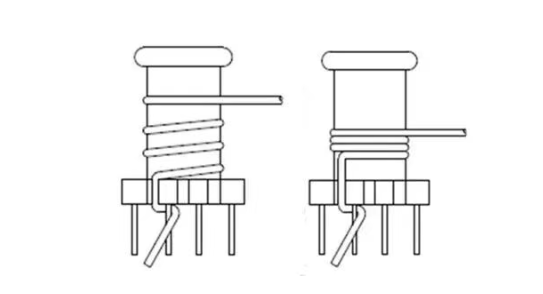
Even with perfectly selected wire gauge, minimal loop area, and clean cable routing, transformer output voltage can still behave unpredictably if the secondary windings are not connected correctly. Many transformers include dual secondary windings so designers can choose between series or parallel configurations. In my experience, wiring mistakes in this area are surprisingly common and can lead to symptoms that look like severe transformer failure. Understanding polarity and the correct method of combining windings is essential for achieving the intended voltage and current ratings.
Wiring Layout Factor 5 – Incorrect Series/Parallel Secondary Wiring
1.Polarity errors causing reduced or zero output voltage
Dual secondary windings have marked polarity indicators, often shown as “•” symbols or numbered terminals such as 1–2 and 3–4. These markings define the direction of the voltage waveform. If the windings are connected out of phase, the two AC voltages oppose one another instead of adding or sharing load.
Common results of incorrect polarity include:
- Near-zero voltage when windings cancel each other in series
- Half voltage when a series connection is made incorrectly
- Circulating current when parallel windings oppose each other
- Overheating of the transformer or wiring due to internal conflict
- Unstable or noisy output voltage during operation
In real projects, I have seen engineers troubleshoot for hours, thinking the transformer was defective, only to find that the secondary wires were flipped in polarity.
2.Correct vs. incorrect series and parallel connection examples
Correct series connection (to double the voltage)
- The end of the first winding connects to the start of the second winding.
- The remaining two free ends become the output terminals.
- Voltage adds properly: V_total = V1 + V2.
Correct example: 1 → 2 connected to 3 → 4 so output is between 1 and 4.
Incorrect series connection
- If 1 connects to 3 instead of 2 connecting to 3, the voltages oppose.
- Result is near-zero or unstable voltage at the output.
This mistake is extremely common during prototyping.
Correct parallel connection (to double the current capacity)
- Start connects to start, end connects to end.
- Both windings must be perfectly in phase.
- Currents share safely without internal conflict.
Correct example: 1 connects to 3 and 2 connects to 4.
Incorrect parallel connection
- Start connected to end by mistake, forming a shorted loop.
- Causes immediate current surge, heating, and severe voltage distortion.
- In many cases, the transformer will hum loudly or trip protection.
I have seen multiple customer samples returned with burned wires or tripped fuses caused entirely by incorrect parallel wiring rather than a transformer defect.
How Wiring Layout Affects Different Types of Transformers?
Although wiring layout principles apply to all transformers, the degree of impact varies widely across different construction types. In my experience working with OEM engineers, the same wiring issue might cause only a small voltage deviation on one transformer type but create a major failure symptom on another. This is because each transformer design has its own magnetic characteristics, leakage inductance behavior, thermal profile, and sensitivity to external wiring. Understanding these differences helps engineers predict how wiring layout will influence real-world performance across various applications.
1.EI Laminated Transformers
EI laminated transformers operate at 50/60 Hz and naturally have higher internal winding resistance and leakage inductance than toroidal or high-frequency types. This makes them more sensitive to wiring resistance and voltage drop under load.
How wiring layout affects them:
- Long wires add significant I·R drop because small VA EI transformers already have modest voltage regulation.
- Large loop area further increases stray inductance, worsening load voltage sag.
- Poor routing near high-current AC lines can introduce audible hum or waveform distortion.
In my experience, most voltage complaints with EI transformers are caused by long cable runs or undersized wiring.
2.Toroidal Transformers
Toroidal transformers have tighter magnetic coupling and lower leakage inductance, which improves their voltage regulation. However, their magnetic field is more concentrated, making them more sensitive to cable routing and noise coupling.
Wiring layout influences them in different ways:
- Long wire length still causes I·R drop, but generally less than EI cores.
- Incorrect routing near switching devices or motor cables can induce noise into the secondary.
- Toroidal cores react more strongly to external magnetic fields due to their closed-loop geometry.
In practice, toroidal designs benefit greatly from clean wiring paths and short wiring distance to the load.
3.Encapsulated PCB Transformers
Encapsulated PCB transformers have fixed pin spacing and controlled leakage inductance, but they often serve low-power applications, which makes them highly sensitive to voltage drop in external wiring.
Key wiring-related issues:V
- Even short wires can cause noticeable voltage drop because the VA rating is small (often 1–5 VA).
- PCB trace resistance becomes part of the wiring layout and must be considered.
- Incorrect polarity when combining secondary pins on the PCB can result in half-voltage or zero-voltage output.
I often see systems passing bench tests but failing in the final enclosure because external wiring and PCB traces add more resistance than expected.
4.High-Frequency Transformers
High-frequency transformers operate in SMPS topologies and handle pulsed, high-speed currents. This makes them especially sensitive to stray inductance, loop area, and magnetic coupling.
How wiring layout impacts them:
- Large loop area between transformer and rectifier increases voltage spikes and reduces effective output voltage.
- Poor routing near noisy switching nodes causes EMI coupling and waveform distortion.
- High-frequency circuits rely heavily on tight wiring and low-impedance paths; any added wiring resistance or inductance degrades performance.
In my experience with SMPS troubleshooting, improper wiring layout around the secondary rectifier and filter is one of the quickest ways to lose voltage regulation or fail EMI compliance.
How To Choose The Right Transformers Supplier?
Choosing the right transformer supplier is essential for stable performance and smooth mass production. In my experience, the best suppliers are not just manufacturers but engineering partners who understand real application challenges.
Here are 5 keys points to look for:
1.Strong Engineering Support
Your supplier should understand transformer design, wiring layout impact, insulation systems, and safety standards.
Unicreed provides direct engineering support from prototype to production.
2.Reliable Manufacturing Quality
Look for in-house winding, insulation control, 100% electrical testing, and traceable materials.
Unicreed, founded in 2008, follows strict testing and OQC processes.
3.Standards and Certification Knowledge
Your supplier must understand EN61558, UL5085, and other relevant requirements.
4.Customization Capability
Good suppliers can tailor EI, toroidal, PCB encapsulated, or high-frequency transformers to your design constraints.
5.Stable Lead Time and Communication
Fast sampling, consistent production, and responsive after-sales support are essential.
In summary, a supplier like Unicreed combines engineering expertise, controlled manufacturing, and dependable service, making the transformer selection process safer and more efficient.
FAQ
1.How can wiring layout change the output voltage of a transformer?
Wiring layout adds extra resistance and inductance in series with the transformer secondary, so the load no longer sees the full rated voltage. Long cables, small wire gauge, narrow PCB tracks and multiple connectors all create voltage drop. In our factory, we often find that “low voltage” issues are actually in the wiring, not in the transformer itself.
2.Does primary-side wiring also affect transformer output voltage?
Yes. If the mains supply to the primary runs through long, thin cables, relays, switches or loose terminals, the primary voltage can sag under load. Since the secondary voltage is proportional to the primary, any drop on the primary side appears as a lower secondary voltage as well. In my experience, cabinets with many series devices on the primary often show this problem.
3.Why are low-voltage secondaries (5–24 V) more sensitive to wiring layout?
Because a small absolute drop is a large percentage of a low voltage. Losing 0.5–1 V in wiring is minor at 48 V, but critical at 5 V or 6 V. That’s why we pay special attention to wiring and PCB copper width on low-voltage, high-current secondaries in our designs.
4.How do wire length and cross-sectional area influence voltage drop?
Voltage drop is roughly proportional to current × resistance, and resistance increases with length and decreases with cross-sectional area (thicker wire = lower R). Long runs of undersized cable can easily create a few percent voltage loss at rated load. As a rule of thumb, for high-current secondaries we keep runs short and choose one or two wire sizes larger than the “bare minimum”.
5.How does rectification and smoothing (DC output) interact with wiring layout?
After a bridge rectifier and capacitor, current is not smooth DC; it flows in high, narrow pulses to charge the capacitor. These peaks are several times the average load current, so all series resistances (wires, tracks, connectors) drop more voltage than simple V = I_DC × R suggests. In my experience, this is why many DC supplies need thicker wiring than the nominal DC current would indicate.
6.What wiring topologies help keep the right voltage on multi-load systems?
For multiple loads fed from one secondary, star wiring (each load returns directly to a common node) is usually better than daisy-chain wiring. Daisy-chaining means the last load sits behind the voltage drops of all the previous connections. We recommend: heavy common bus or star point for high currents, and short branches to each load.
7.How can I quickly diagnose if wiring layout is the cause of low output voltage?
Three simple steps:
- Measure voltage at the transformer secondary pins (no-load and full-load).
- Measure at the PCB input and at the load terminals under the same conditions.
- Compare the values and calculate the drop along each segment.
If most of the loss is between transformer and load, the wiring layout is the culprit, not the transformer design.
8.What design rules should I follow to minimize wiring-related voltage drop?
- Set a voltage-drop budget (e.g. max 3–5% from transformer to load).
- Keep high-current paths short and thick (larger wire gauge, wide copper pours).
- Minimize the number of connectors and terminal blocks in series.
- Use star distribution for multi-load systems rather than daisy-chaining.
At unicreed, whenever we design a transformer for OEM customers, we always ask about cable length, wire size, and PCB layout, because these details decide whether the rated voltage actually reaches the load.
Conclusiontransformer output voltage
Transformer output voltage is never determined by turns ratio alone. As we have discussed, wire length, wire gauge, contact resistance, loop geometry, magnetic coupling, and even simple polarity mistakes can all change the voltage that finally reaches your load. In my experience, many “transformer problems” are actually system layout problems. When current flows, every milliohm and every routing decision matters.
Whether you are using an EI laminated transformer, toroidal transformer, encapsulated PCB unit, or a high frequency design, the final performance always depends on the complete current path, not just the transformer itself. That is why proper layout evaluation, load analysis, and real-condition testing are critical before finalizing your design.
At Unicreed, we support OEM customers not only with transformer manufacturing, but also with practical engineering guidance from sample stage to mass production. If you are experiencing voltage drop, unstable output, or regulation concerns, share your application parameters with us. Our engineering team will help you analyze the root cause and recommend the right solution.
Contact Unicreed today to optimize your transformer performance with confidence.
Related Transformer Articles:
- How Harness Length, Wire Gauge, and Twisting Affect Transformer Output Voltage?
- How To Choosing the Right Dual Primary or Secondary Windings for Your Transformer Design?
- How to Improve Leakage Inductance Performance in High-Frequency Transformers?
- What Parameters Should You Consider When Selecting a High-Frequency Transformer?
- 5 Ways Unicreed Customizes Transformers for Your System
