Have you ever wondered why some transformers stay cool and quiet for years while others fail early or generate unwanted noise and heat? One common culprit is poor winding technique, especially in toroidal transformers. These donut-shaped cores are known for their compact size, low electromagnetic interference, and high efficiency, but only if they’re wound correctly.
At Unicreed, we’ve seen how even small winding flaws can lead to big problems like excessive losses, voltage drop, or insulation failure. That’s why we treat copper wire winding as both a science and a craft. Our approach isn’t just about wrapping wire. It’s about engineering each turn for maximum performance, reliability, and compliance.
In this blog, I’ll walk you through how we wind copper wire for our toroidal transformers and why our method delivers superior efficiency, reduced heat, and longer life in demanding applications.
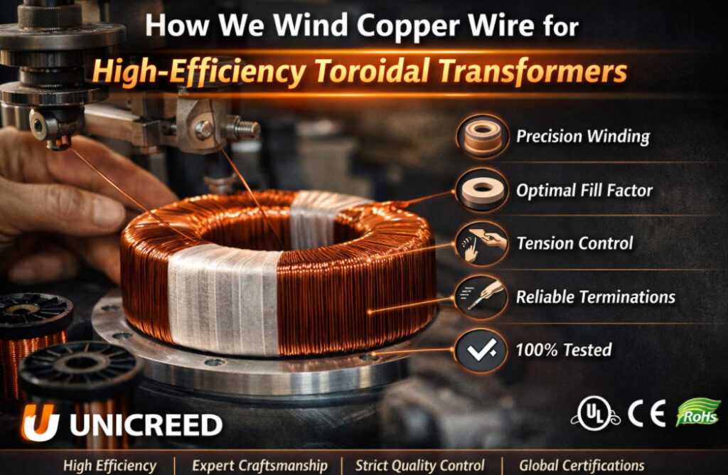
Winding copper wire for toroidal transformers isn’t just about wrapping wire around a core. It’s a detailed engineering process that directly impacts performance, efficiency, and reliability. At Unicreed, we follow a disciplined, step-by-step method to ensure every transformer delivers maximum efficiency with minimal energy loss. If you’re aiming for high-performance results in demanding applications, the following nine tips reflect the practical principles we use to get it right from the very beginning:
- Step 1,Start from the real load waveform (RMS current, not nameplate current)
- Step 2, Choose conductor strategy for low loss and repeatable winding
- Step 3,Design the winding plan before touching the core
- Step 4 ,Window utilization and fill factor (where efficiency is won or lost)
- Step 5, Winding tension control: the silent driver of loss and reliability
- Step 6,Layering, turn placement, and minimizing hot spots
- Step 7,Impregnation/varnish: when it improves efficiency (and when it can trap heat)
- Step 8,Termination craftsmanship: efficiency can fail at the joint
- Step 9,The test gates we use to protect efficiency and safety
What “High Efficiency” Really Means for Toroidal Transformers
High efficiency is not just a marketing term. In toroidal transformer design, it is the result of precise planning, smart material choices, and disciplined manufacturing. At Unicreed, we take efficiency seriously because every wasted watt becomes heat, which affects performance, lifespan, and safety. To build truly high-efficiency transformers, we focus on where energy loss occurs and what we can control before we even start winding. Here is what high efficiency really means in our process.
1.Efficiency Breakdown: Where the Watts Go
Copper Loss (I²R)
Copper loss is caused by resistance in the wire. The higher the resistance, the more energy is lost as heat. We minimize this by:
- Choosing the correct wire gauge based on real RMS current
- Maximizing packing density while avoiding insulation damage
- Controlling winding layout to prevent hot spots
Even small improvements in winding design can reduce copper loss and improve total efficiency.
Core Loss
Core loss depends on how the magnetic field flows through the core. It is influenced by:
- Flux density: We design for optimal flux levels to reduce hysteresis and eddy current losses
- Core material: We use consistent, high-quality toroidal cores with low loss at 50Hz or 60Hz
- Mains frequency: All calculations match the operating frequency to avoid excess saturation or noise
Selecting the right core and operating conditions helps us keep losses low while maintaining performance.
Stray Loss
Stray losses happen when leakage flux escapes and heats nearby metal parts. These losses can be hard to measure but are very real. We reduce them by:
- Designing compact winding layouts to control leakage
- Using short lead wires and clean terminations
- Avoiding sharp routing angles that increase flux leakage
A good transformer is not just efficient on paper. It performs cleanly in the real application.
2.The Specs We Confirm Before Winding
We do not guess or assume. Before any copper is wound, we confirm the full electrical and thermal specifications.
Input
- Input voltage and frequency (50 or 60 Hz)
- Acceptable no-load current for standby performance
Output
- Required voltage and load current on each winding
- Duty cycle: continuous, intermittent, or variable
Thermal
- Ambient temperature in real use, not just lab conditions
- Maximum allowable temperature rise based on insulation class
- Target insulation system (Class B, F, or H)
Safety
- Hi-pot test level the transformer must pass
- Required creepage and clearance distances
- Class I or Class II construction, with or without protective earth
This structured process ensures that every winding we make supports the goal of high efficiency, safety, and long-term reliability.
Experience note: In my experience, customers often under-estimate VA when the load is “rectifier + big capacitor”. The transformer runs hotter and efficiency drops because RMS current is much higher than expected.
Step 1,Start from the real load waveform (RMS current, not nameplate current)
Every high-efficiency winding begins with a solid understanding of the real electrical demands. At Unicreed, we never rely on guesswork or nameplate ratings. Before we select wire or touch the core, we study how the transformer will be used. This helps us avoid underestimating current, overheating under load, or missing safety requirements. Here is how we approach this first and most important step.
Step 1: Start from the Real Load Waveform
Resistive vs Rectifier + Capacitor Input Loads
Not all loads behave the same. A resistive load draws smooth, sinusoidal current, and its RMS value matches the average. But rectifier and capacitor input circuits common in power supplies draw short, sharp pulses. These create much higher RMS current, even if the average power seems low.
If we sized the wire based only on the average current, the transformer would overheat under real operating conditions. That is why we always calculate based on true RMS current.
Continuous vs Intermittent Duty
A transformer that runs 24 hours a day needs a very different winding strategy than one that operates in short bursts. The thermal time constant matters. For continuous duty, we select wire and insulation that can handle the long-term heat buildup. For intermittent loads, we might allow slightly higher peak current but still ensure temperature stays within safe limits over time.
Ambient and Enclosure Conditions
Ambient temperature plays a huge role in heat management. A transformer in open air at 25 degrees Celsius can dissipate heat much more easily than one sealed in a control cabinet at 50 to 70 degrees.
We factor in the real environment when calculating temperature rise and current density. This ensures that the copper wire does not overheat, even under worst-case conditions.
Safety Requirements
Before winding, we also confirm the transformer’s safety class and test levels. This includes:
- Hi-pot voltage requirements for dielectric testing
- Creepage and clearance distances between conductors
Whether the design must meet Class I (with protective earth) or Class II (double insulation) standards
These factors determine insulation type, winding layout, and lead treatment. Starting with this full understanding helps us avoid compliance issues later
Experience note: When customers quote only DC current, we insist on the front-end topology because that’s where copper loss calculations go wrong.
Step 2, Choose conductor strategy for low loss and repeatable winding
After understanding the real load and thermal environment, the next step is to choose the right conductor strategy. This decision affects not only electrical efficiency but also how easy and reliable the winding process will be. At Unicreed, we balance performance, manufacturability, and durability by selecting wire types that support consistent production and long-term transformer reliability. Here’s how we make those choices.
Step 2: Choose Conductor Strategy for Low Loss and Repeatable Winding
Solid Magnet Wire
This is the most common choice for toroidal transformers, especially at lower current levels. It provides excellent packing density and clean layering. However, when the required current increases and the wire diameter grows, solid wire becomes more difficult to bend, increasing the risk of enamel damage during winding.
2-in-Hand or 3-in-Hand (Parallel Wires)
To avoid using one large, stiff conductor, we often use two or three smaller wires in parallel. This technique offers several benefits:
- Easier winding with less stress on the enamel
- Reduced chance of mechanical damage during tight turns
- Better fit inside the toroidal core, improving fill factor and layering control
- More even current distribution in the winding at 50Hz or 60Hz
Parallel wires are especially useful when the transformer carries higher current but needs to remain compact and reliable
Stranded “Flexibility Bundles”
In some cases, we use flexible bundles made from multiple thin strands. These are not true Litz wire but are chosen for their mechanical handling benefits. They offer better flexibility than solid wire, which can be helpful in tight or high-turn-count designs.
However, we apply them carefully, because:
- They take more space, reducing winding fill factor
- They are more difficult to terminate consistently
- Their insulation layers must be managed to avoid uneven tension or weak spots
Why Parallel Wires Reduce Defects and AC Loss
When conductor size increases, both winding difficulty and AC resistance (due to skin effect) increase. Using parallel wires allows us to:
- Wind with lower mechanical stress
- Reduce internal heating
- Minimize defect rates from insulation cracking or poor termination
This approach supports both high efficiency and reliable production, which is exactly what we aim for at Unicreed.
Experience note: If the wire feels “springy” and won’t seat at the inner diameter, yield drops fast—switching to parallel wires usually stabilizes production.
Step 3,Design the winding plan before touching the core
Before a single turn of copper is wound, we always finalize the full winding plan. This step is essential for performance, safety, and process repeatability. At Unicreed, we believe that careful planning up front prevents problems during manufacturing and ensures a clean, reliable transformer build. A well-designed winding plan addresses electrical layout, insulation strategy, and how the leads will exit the core. Here is how we approach this step.
Step 3: Design the Winding Plan Before Touching the Core
Turns Plan
We begin by mapping out the full turns layout, which includes:
- The sequence of windings, such as primary first, then secondary
- How split secondaries will be placed for balance and symmetry
- Placement of taps, which need to be accurate and stable
- Ensuring magnetic and thermal balance to avoid hot spots or noise
This helps us maintain precise voltage outputs and consistent performance from unit to unit.
Next, we define the insulation layers between windings:
- Choosing the right tape type based on voltage class and thermal rating
- Applying margin tape to maintain creepage distances at the core edge
- Adding insulation barriers when winding low-voltage and high-voltage sections on the same core
We never rely only on wire enamel for isolation. A strong insulation plan ensures dielectric strength and long-term reliability.
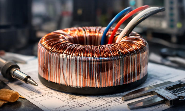
Lead Exit Strategy
Finally, we plan how the wires will exit the toroid:
- Defining the routing path to avoid crossing or pinching
- Selecting proper sleeving to protect against abrasion or electrical stress
- Designing for strain relief to prevent wire fatigue or breakage under handling or vibration
This step also supports better safety compliance and makes assembly easier at the next stage of the production line.
Experience note: Most hi-pot failures are born in the winding plan lead dress and tape coverage matter more than one extra enamel grade.
Step 4 ,Window utilization and fill factor (where efficiency is won or lost)
Once the winding plan is in place, we shift our focus to how the wire physically fits into the core. This is where many theoretical designs run into real-world challenges. At Unicreed, we take window utilization seriously, because this is where transformer efficiency is either protected or compromised. A smart fill factor ensures optimal copper usage without overpacking the core, which can lead to defects, wasted material, or even performance loss. Here is how we manage this critical step.
Step 4: Window Utilization and Fill Factor – Where Efficiency Is Won or Lost
Why a Theoretically Correct AWG May Not Work
Wire size calculators might tell you that a certain AWG fits your current perfectly, but in practice, that same wire might be too stiff or bulky to wind cleanly around a toroidal core. If you try to force it, you risk enamel damage, poor layer formation, and inconsistent tension.
We often find that slightly smaller wire in parallel (such as 2-in-hand) provides better results. It allows for more consistent winding tension and improves manufacturability without sacrificing electrical performance.
How Packing Affects Efficiency
Packing is not just about getting the wire into the core it directly affects efficiency:
- Tight but controlled winding reduces copper length and resistance
- Overpacked windings can trap heat, create hot spots, and cause thermal imbalance
- Poor packing with too much space leads to vibration, mechanical instability, and inefficient use of the core window
We always aim for a balance: dense enough to be efficient, but not so tight that reliability is at risk.
Practical Fill-Factor Checks
To ensure good fill without problems, we always check:
- Room for interlayer tape and insulation where needed
- Extra space at exits for sleeving, lead routing, and strain relief
Termination area size to accommodate joints, crimps, or soldering without crowding the winding
By building in these margins from the start, we avoid rework, improve consistency, and keep transformer losses low.
Experience note: I’ve seen larger wire increase resistance in practice because messy packing forces longer routing and poor layer formation.
Step 5, Winding tension control: the silent driver of loss and reliability
One of the most overlooked factors in toroidal transformer winding is tension control. You can select the perfect wire, plan your layout, and use high-grade materials but if the winding tension is off, the entire transformer’s performance and reliability can suffer. At Unicreed, we treat tension control as a critical process parameter, not just a setup detail. Here’s how we manage it and why it matters.
Step 5: Winding Tension Control – The Silent Driver of Loss and Reliability
Tension Too High
Excessive tension during winding can cause:
- Micro-damage to enamel insulation, which may not show up immediately but leads to hi-pot test failures
- Increased defect rates, especially when bending large-gauge wire through tight curves
- Long-term reliability issues due to internal stress points in the winding
We often find that overly tight winding is a hidden cause of early-life transformer failures, especially in high-voltage applications.
Tension Too Low
Low tension creates another set of problems:
- Loose windings can shift during transport or under load
- This leads to audible hum, mechanical wear, and thermal hotspots
- Movement under inrush current may also cause insulation abrasion or lead displacement
A transformer that looks good at the factory can fail later if the windings are not properly tensioned and compacted.
How We Control Tension at Unicreed
We manage winding tension through a combination of:
- Defined process windows: Each transformer model has a tested range of acceptable winding tension, based on conductor type and core size
- Operator training: Our technicians are trained to detect and adjust for correct wire feel, feed rate, and pull strength during winding
- Specialized tooling: We use calibrated winding machines with tension adjustment features to ensure consistency across batches
Experience note: On toroids, the inner radius is where enamel damage happens first tension control is non-negotiable.
Step 6,Layering, turn placement, and minimizing hot spots
Even when the right wire and correct tension are in place, poor layering can silently reduce transformer efficiency and reliability. At Unicreed, we pay close attention to how every turn is placed, how each layer builds up, and how heat moves through the winding. Proper layout does more than look clean it controls thermal behavior, reduces mechanical stress, and helps the transformer maintain performance over time. Here is how we do it.
Step 6: Layering, Turn Placement, and Minimizing Hot Spots
Avoiding Crossovers and Sharp Bends
Crossed wires or sharp directional changes create two serious risks:
- Mechanical stress, which can damage enamel insulation during winding or over time due to vibration
- Uneven current distribution, which causes localized heating or noise
We train our winding team to maintain smooth, controlled turns and avoid stacking wires or forcing tight bends, especially near the core edges.
Consistent Layer Build-Up
Each layer of winding must be evenly distributed, with no bulging areas or thin spots. When layers are inconsistent:
- Pressure concentrates in certain areas, damaging insulation or compressing underlying turns
- Air pockets may form, trapping heat and raising local temperatures
Our process ensures tight but uniform layers, which leads to better thermal performance and higher reliability.
Managing Thermally Critical Zones
Some parts of a toroidal transformer are more vulnerable to heat and movement. We pay extra attention to:
- Inner diameter: Where space is tight and cooling is most limited
- Termination zones: Where thicker joints and sleeving can cause heat build-up
- Lead exits: Where wires transition from winding to external connection, often exposed to handling or vibration
Experience note: When we do thermal checks, the hot spot is often not “mid-winding”—it’s near the lead exit or a compressed inner layer.
Step 7,Impregnation/varnish: when it improves efficiency (and when it can trap heat)
Once the winding is complete, the next step is securing the structure for long-term stability and performance. At Unicreed, we carefully apply impregnation or varnish to enhance mechanical strength, reduce vibration, and improve electrical insulation. But while this process offers major benefits, it must be balanced with thermal management. Applying too much or using the wrong materials can actually hurt efficiency. Here is how we get it right.
Step 7: Impregnation/Varnish – When It Improves Efficiency and When It Can Trap Heat
Goals of Impregnation
Proper varnishing helps us achieve three key results:
- Reduce vibration and noise by locking the windings in place
- Improve dielectric strength, supporting hi-pot performance and long-term insulation integrity
Stabilize the winding mechanically, especially in applications with vibration, frequent start-stops, or transport movement
A well-impregnated winding resists movement and maintains performance even under thermal cycling or mechanical stress
The Trade-Off: Thermal Implications
Impregnation must be carefully controlled. Excessive varnish, too many insulation layers, or tight potting can:
- Trap heat inside the winding
- Prevent natural airflow or thermal conduction
- Increase the overall temperature rise during operation
Before finalizing a design, we always test how the varnish affects heat dissipation. This way, we avoid sacrificing thermal performance for mechanical strength.
Material Compatibility and Cleanliness
The varnish or resin system must bond well with the copper wire and insulation materials. For that to happen, the winding surface must be clean and free of:
- Dust, oil, or residue from handling
- Winding debris or enamel flakes
- Incompatible tape or sleeving that may resist wetting
If the varnish doesn’t wet the surface properly, it leaves air pockets or weak spots that reduce insulation quality. That is why we maintain strict cleanliness standards during winding and handle all materials with care.
Experience note: We’ve seen “noise fixes” backfire thermally when impregnation or tight wrapping reduces heat escape so we re-validate temperature rise after any process change.
Step 8,Termination craftsmanship: efficiency can fail at the joint
Even the best-wound transformer can underperform or fail if the terminations are not handled correctly. At Unicreed, we treat termination work as a key part of our quality process not just the final step. Good termination protects efficiency, improves reliability, and ensures the unit passes electrical testing without surprises. Here’s how we approach this often underestimated detail.
Step 8: Termination Craftsmanship – Efficiency Can Fail at the Joint
Joint Resistance and Local Heating
A poor connection at the wire terminal creates a bottleneck. Even a small increase in resistance at the joint can:
- Generate localized heat
- Cause voltage drops under load
- Lead to long-term degradation, especially in high-current applications
That’s why we inspect every connection for both mechanical integrity and electrical consistency.
Solder vs Crimp vs Lead Splice
Different applications call for different termination techniques. We select based on reliability, current level, and production repeatability:
- Solder joints are common in low to medium current units but must be well-wetted with no cold joints
- Crimp terminals are ideal for higher current and allow better mechanical stress relief
- Lead splices are used when extending or converting winding leads to hookup wire
Each method has its own process controls, and we ensure every joint is checked for consistency and strength.
Parallel Wire Equalization
When using parallel wires, proper termination becomes even more important. If wires are stripped unevenly or cut to different lengths:
- Current may not split evenly
- One wire may overheat while others carry less load
- The joint may fail under thermal cycling
We use controlled stripping tools and ensure symmetric lead lengths to balance current across all wires. This helps maintain the efficiency we worked hard to build throughout the winding process.
Experience note: A perfect winding can still run hot if one termination is weak—termination is part of the conductor design, not an afterthought.
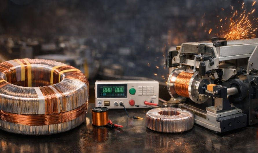
Step 9,The test gates we use to protect efficiency and safety
No matter how well a transformer is designed and wound, its performance must be verified through testing. At Unicreed, we don’t rely on sampling we test every single unit to confirm that it meets both electrical and safety requirements. These test gates ensure that what we deliver performs exactly as expected in your system, even under demanding conditions. Here’s what we check before a transformer leaves our factory.
Step 9: The Test Gates We Use to Protect Efficiency and Safety
100% Electrical Parameter Checks
Every transformer goes through full electrical testing, including:
- Turns ratio and output voltage to ensure accuracy under load
- Winding resistance to confirm correct wire size, turns count, and tight connections
- No-load current where applicable, especially important for low-loss or energy-saving designs
These tests verify that each unit delivers the performance required no surprises in the field.
Hi-pot and Insulation Resistance Tests
To protect user safety and product reliability, we perform:
- Hi-pot tests to validate the dielectric strength between windings and from winding to core
- Insulation resistance checks to confirm that no moisture, contamination, or winding damage has compromised the system
These tests help detect hidden defects like enamel cracks or insulation failure that could cause field breakdowns.
Temperature Rise Validation
During the prototype phase and whenever we make a design change, we run thermal validation tests. We simulate worst-case load conditions and enclosure environments to:
- Confirm that temperature rise stays within insulation class limits
- Ensure that winding choices do not lead to unexpected hot spots
This step is critical for long-term reliability, especially in compact or enclosed systems.
Noise and Vibration Check
For applications like audio systems or medical devices, we also include a noise check to catch:
- Loose windings
- Vibration under load
- Core or winding movement that could lead to hum or rattle
Experience note: We treat test data as process feedback—when a trend shifts, it usually points to tension, packing, or termination drift.
What Are The Common Winding Mistakes And How Do We Prevent Them?
Even with the best materials, a transformer can fail if the winding process is not carefully controlled. At Unicreed, we have studied the most common mistakes that lead to inefficiency, safety risks, or early failure. We have built safeguards into every stage of our process to avoid them. Here are the key winding errors we see in the industry and how we prevent them to ensure consistent, high-quality results.
What Are the Common Winding Mistakes and How Do We Prevent Them?
1.Underestimating RMS Current
The problem: Designing around average current or nameplate values can lead to undersized wire, especially with pulsed loads. This causes overheating and poor efficiency.
Our solution: We always calculate with true RMS current based on real-world waveforms and duty cycles. This ensures the wire can handle both thermal and electrical demands.
2.Using Overly Thick Wire
The problem: Choosing one large wire for high current may seem efficient, but it makes winding harder, reduces packing quality, and can create hot spots or noise.
Our solution: We often use parallel wires such as 2-in-hand or 3-in-hand. This improves packing density, manages AC losses, and reduces mechanical stress during winding.
3.Loose Winding
The problem: Inadequate winding tension allows movement under load or vibration. This leads to audible hum, insulation wear, or long-term reliability issues.
Our solution: We maintain strict tension control through tooling, trained operators, and documented processes to ensure consistent and stable windings.
4.Tape Gaps and Sharp Edges
The problem: Poor insulation tape application or routing wires over sharp edges can cause hi-pot failures and reduce dielectric integrity.
Our solution: We design clear insulation plans using margin tape, barrier layers, and smooth routing paths to protect every winding section.
5.Bad Termination
The problem: Poor joints, whether cold solder, uneven crimps, or mismatched leads, can cause localized heating and voltage drop, especially in high-current sections.
Our solution: We apply standardized termination techniques and quality inspections. This ensures every joint is solid, balanced, and reliable.
Why Choose Unicreed?
At Unicreed, we do not just manufacture toroidal transformers. We engineer them for long-term performance, efficiency, and reliability. Our strength lies in precision winding, high-quality materials, and strict process control. Every decision we make, from copper sourcing to final testing, reflects our commitment to product excellence.
1) Engineering-first approach to “high efficiency”
In my experience, high efficiency is achieved when flux density, conductor strategy, and insulation design match the real load waveform and thermal environment. I work from a loss budget and practical manufacturing limits, not only a theoretical VA number.
2) A real transformer factory with disciplined processes
Unicreed is based in Xiamen and has focused on transformer manufacturing since 2008. In our production line, winding, insulation, termination, and impregnation are controlled processes with clear standards, not luck or personal habits.
3) Consistency from prototype to mass production
A good sample is easy. Stable batches are hard. We control the factors that usually drift, including winding tension, layer uniformity, lead exit handling, and termination consistency, so resistance, no-load current, and temperature rise stay predictable.
4) Safety and quality gates built into production
We implement electrical checks as process gates, and we apply hi-pot and insulation verification per your specification to catch defects early and reduce field risk.
5) OEM and ODM support that is practical
For custom toroidal requests such as multi-secondaries, taps, low-noise builds, tight space designs, or high-ambient control cabinets, I help define the winding plan, insulation plan, and validation tests in a clear order so prototypes converge faster.
6) B2B documentation and traceability support
We can support specifications, drawings, and test-related records based on your project needs, and we maintain batch-level control for production consistency.
If you share your primary and secondary voltages, load type (especially rectifier plus capacitor or not), RMS current or waveform, duty cycle, ambient and enclosure temperature, and safety intent (Class I or Class II, hi-pot requirement), I will recommend a winding strategy that balances efficiency, cost, and manufacturability.
Conclusion
Winding copper wire for toroidal transformers is not just a step in production. It is a critical part of ensuring performance, safety, and long-term reliability. Every detail, from wire selection and tension control to insulation and termination, contributes to building a high-efficiency transformer that meets real-world demands.
At Unicreed, I make sure our winding process is precise, consistent, and aligned with global quality standards. That is how we deliver transformers with low energy loss, stable output, and dependable operation across a wide range of industries.
If you are looking for reliable designs, I invite you to browse our Toroidal Transformer Catalog. And if you need a custom winding solution or want to discuss your technical requirements, feel free to contact me. I am here to help you create the right transformer for your application.
Related Transformer Articles:
- Everything You Should Know About Copper Wire in Toroidal Transformers
- How To Choosing the Right Dual Primary or Secondary Windings for Your Transformer Design?
- What Are Thermal Class Ratings in Toroidal Transformers?
- How Encapsulation Enhances Performance in Toroidal Transformer Construction?
- 11 Questions to Ask Before Purchasing a Toroidal Transformer
