Are you struggling to find the perfect high-frequency transformer for your application? The wrong choice could mean inefficiency, performance bottlenecks, or even safety risks. High-frequency transformers are the backbone of modern electronics, ensuring precise energy transfer in applications ranging from renewable energy systems to critical medical devices.
Selecting the right transformer isn’t just about ticking boxes—it’s about optimizing performance, ensuring efficiency, and meeting safety standards. Whether you’re designing a cutting-edge industrial control system or a next-gen renewable energy solution, the stakes are high.
In industries like healthcare, industrial automation, and clean energy, high-frequency transformers play an indispensable role. Getting the selection right could be the key to delivering reliability and innovation in these demanding fields.
In this blog, I’ll show you the key parameters to consider when selecting a high-frequency transformer, so you can make a choice that ensures success for your application and industry.
Understanding the Key Parameters of High-Frequency Transformers
- Inductance
- Leakage Inductance
- Turns Ratio
- Phase
- DC Resistance (DCR)
- Quality Factor (Q Value)
- HI-Pot (High Potential) Testing
- Insulation Impedance
Understanding Inductance
Have you ever wondered why the inductance of a transformer is so crucial to its performance? This seemingly simple parameter determines how efficiently a transformer can store and transfer energy, making it one of the foundational aspects of transformer design.
Let’s explore how inductance is defined and what influences it.
Inductance in a transformer typically refers to the inductance of the primary winding. It is influenced by the core material, its shape and size, and the air gap within the core. In transformers with air gaps, the inductance tends to remain stable, even under varying conditions. Precision is key—under normal circumstances, the tolerance of inductance can be maintained within 5%, ensuring reliable operation. Measurements are usually conducted at test frequencies of 20 kHz, 50 kHz, or 100 kHz, depending on the application.
By carefully managing inductance, you can achieve optimal energy storage and transfer, ensuring your transformer performs efficiently across a wide range of conditions.
Understanding Leakage Inductance
Have you ever wondered why transformers sometimes generate unintended energy losses or interference? This phenomenon often stems from leakage inductance, a critical parameter that can significantly affect transformer performance.
Let’s explore what leakage inductance is and why it matters.
Leakage inductance occurs because the magnetic flux generated by the primary winding does not fully couple with the secondary winding. This uncoupled flux results in energy losses and creates a phenomenon known as back electromotive force (EMF) during the switching-off phase of a circuit. If not properly controlled, this back EMF can cause overvoltage, potentially damaging switching devices. Additionally, excessive leakage inductance contributes to electromagnetic interference (EMI), disrupting nearby electronic systems.
To minimize leakage inductance, designers often use techniques like the “sandwich winding method,” which involves interleaving the primary and secondary windings. This reduces the magnetic path length for uncoupled flux, improving coupling efficiency and reducing associated risks.
Understanding Turns Ratio
Do you know how a transformer efficiently steps up or steps down voltage? The answer lies in its turns ratio—a fundamental parameter that directly determines the voltage transformation.
Let’s explore how the turns ratio works and why it’s so important.
The turns ratio is the ratio of the number of windings (or turns) in the primary coil to the number in the secondary coil. In most practical applications, transformers are used to step down voltage. As a result, the primary winding, handling higher voltage, typically has more turns, while the secondary winding, delivering lower voltage, has fewer turns.
This configuration ensures that the voltage is transformed effectively while maintaining energy balance (considering power equals voltage multiplied by current). A well-chosen turns ratio is critical to match the input and output voltage requirements, whether for industrial systems, power supplies, or renewable energy applications.
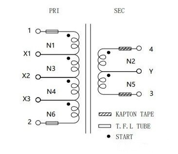
| NO. | Winding Name | Starting terminal | Turns | Wire SPEC | Tape turns | Winding method | Remark |
| 1 | N0 | 1.5Ts | Use T0.25*23mm NOMEX making bobbin | 1 | Close winding | X1,X3,Y are | |
| 2 | N1 | 1-X1 | 10Ts | 0.06450P1C 2UEWH LITZ | 1 | Close winding | fly wire, |
| 3 | N2 | 4-Y | 8Ts | 0.1300P1C 2UEWH Mylar | 1 | Close winding | Flying leads |
| 4 | N3 | X1 – X2 | 10Ts | 0.06450P1C 2UEWH LITZ | 1 | Close winding | need to be |
| 5 | N4 | X2 – X3 | 10Ts | 0.06450P1C 2UEWH LITZ | 1 | Close winding | insulated with |
| 6 | N5 | Y-3 | 8Ts | 0.1300P1C 2UEWH Mylar | 1 | Close winding | tape or |
| 7 | N6 | X3 -2 | 10Ts | 0.06450P1C 2UEWH LITZ | 1 | Close winding | sleeving |
Understanding Phase
Have you ever wondered why transformers have designated terminal markings like dots or polarity labels? These markings indicate the phase relationship between windings, a crucial factor that ensures the correct operation of the transformer in complex circuits.
Let’s explore what phase means in transformers and why it matters.
Phase, also referred to as polarity or the “like terminals,” describes the relative orientation of the start and end points of the windings. When windings are wound in the same direction, the starting points (designated as the like terminals) have the same polarity. Conversely, if the windings are wound in opposite directions, the like terminal on one winding will correspond to the endpoint of the other.
During the winding process, careful attention must be paid to the insertion direction and alignment of the machine to maintain proper polarity. Incorrect phase relationships can result in undesirable outcomes, such as voltage imbalances or even circuit failures in applications like push-pull or parallel transformers.
By ensuring the correct phase alignment, designers can avoid these challenges, ensuring reliable performance across various applications.
Understanding DC Resistance (DCR)
Do you know how a transformer’s winding material impacts its temperature rise and efficiency? This is closely tied to DC resistance (DCR), a key parameter that directly affects energy losses and thermal performance.
Let’s explore what DCR is and why it’s critical in transformer design.
DCR is determined by the wire’s diameter (gauge) and the number of turns in the winding. Essentially, it represents the resistance encountered by direct current flowing through the windings. High DCR leads to increased copper losses, resulting in heat generation and higher operating temperatures. Testing DCR is a critical step in transformer manufacturing—it ensures that the correct wire gauge is used during winding, preventing performance issues caused by deviations.
By monitoring and optimizing DCR, manufacturers can minimize energy losses, enhance thermal stability, and improve the overall efficiency and reliability of the transformer. This step is vital for applications where consistent performance and durability are non-negotiable.
Understanding Quality Factor (Q Value)
Have you ever wondered how to measure the efficiency of a transformer in terms of energy storage versus losses? The quality factor, or Q value, provides this insight, making it a key indicator of magnetic performance and material quality.
Let’s explore what the Q value is and how it impacts transformer performance.
The Q value reflects the level of magnetic loss and overall quality of the transformer. It is inversely related to inductance—the higher the inductance, the lower the Q value for a given product. Additionally, the Q value is frequency-dependent: as the operating frequency increases, the Q value also rises. This means that transformers designed for high-frequency applications typically exhibit higher Q values, ensuring better performance with minimal energy dissipation.
Understanding and optimizing the Q value is essential for balancing inductance and efficiency, especially in applications where frequency plays a critical role, such as power supplies and communication systems.
Understanding HI-Pot (High Potential) Testing
Have you ever wondered how transformers prevent catastrophic failures like insulation breakdown or short circuits during operation? This is where HI-Pot (High Potential) testing becomes essential, ensuring the durability and safety of transformers under high-voltage conditions.
Let’s explore what HI-Pot testing is and why it matters for transformer performance.
HI-Pot testing evaluates the insulation strength between windings (e.g., primary and secondary) and between windings and the core. It helps prevent electrical breakdown that could lead to overheating or even transformer failure. The primary-to-secondary insulation typically has the highest voltage withstand requirements. To meet these demands, one winding is often constructed with triple-insulated wire, or barriers are added to increase creepage distance and improve safety.
By ensuring transformers pass rigorous HI-Pot testing, manufacturers can guarantee reliability, compliance with safety standards, and peace of mind for applications where electrical insulation is critical.
| NO. | Name | Test Terminal | Test value | Test Conditions | Standard Testing Instruments |
| 1 | Inductance | 1–2 | 141uH +5% | 100kHz,1.0V | 11050 |
| 2 | Leakage Inductance | 1–2 connect others PIN | 3.0 uH MAX | 100kHz,1.0V | 11050 |
| 3 | DCR | 1-2 | 65 mΩ MAX | 25℃ | 16502 |
| 4 | DCR | 3-4 | 12 mΩ MAX | 25℃ | 16502 |
| 5 | Turn Ratio | (N1+N3+N4+N6):(N2+N5) | 40:16 | 20KHZ,1.0V | 11050 |
| 6 | Withstand Voltage | Primary – Secondard | 3000VAC | 1mA,60sec,50Hz | 19055 |
| 7 | Withstand Voltage | widing – core | 1500VAC | 1mA,60sec,50Hz | 19055 |
Understanding Insulation Impedance
Have you ever wondered how transformers maintain circuit stability and prevent electrical leaks? The answer lies in insulation impedance, a critical factor that ensures safe and reliable operation in high-voltage environments.
Let’s explore how insulation impedance works and why it’s essential.
Insulation impedance refers to the ability of an insulating material to resist electrical current flow. It directly impacts the transformer’s capacity to isolate circuits and maintain operational stability. Alongside withstand voltage—the maximum voltage the insulation can endure—insulation impedance determines the quality and reliability of the transformer. These parameters are often tested together to ensure that the insulation can block undesired current effectively, protecting the system from short circuits and instability.
By prioritizing high insulation impedance and robust withstand voltage, manufacturers can deliver transformers capable of withstanding demanding applications, from industrial control systems to medical equipment, ensuring safety and longevity.
Conclusion:
Choosing the right high-frequency transformer is a pivotal step in ensuring your application’s success. From key parameters like inductance, leakage inductance, and turns ratio to critical aspects such as DC resistance, quality factor, HI-Pot testing, and insulation impedance, each factor plays a significant role in determining performance, efficiency, and safety.
Prioritizing quality and precision isn’t just a recommendation—it’s a necessity. A high-quality transformer tailored to your application can minimize energy losses, enhance reliability, and meet safety standards, making all the difference in industries where excellence is non-negotiable.
At Unicreed, we understand the importance of precision-engineered transformers. Our range of high-frequency transformers is designed to meet diverse needs with unmatched quality. If you’re ready to elevate your systems with a reliable transformer, explore our products or contact our team today for personalized guidance and support. Let’s power your innovation together!
