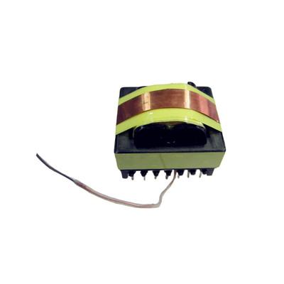
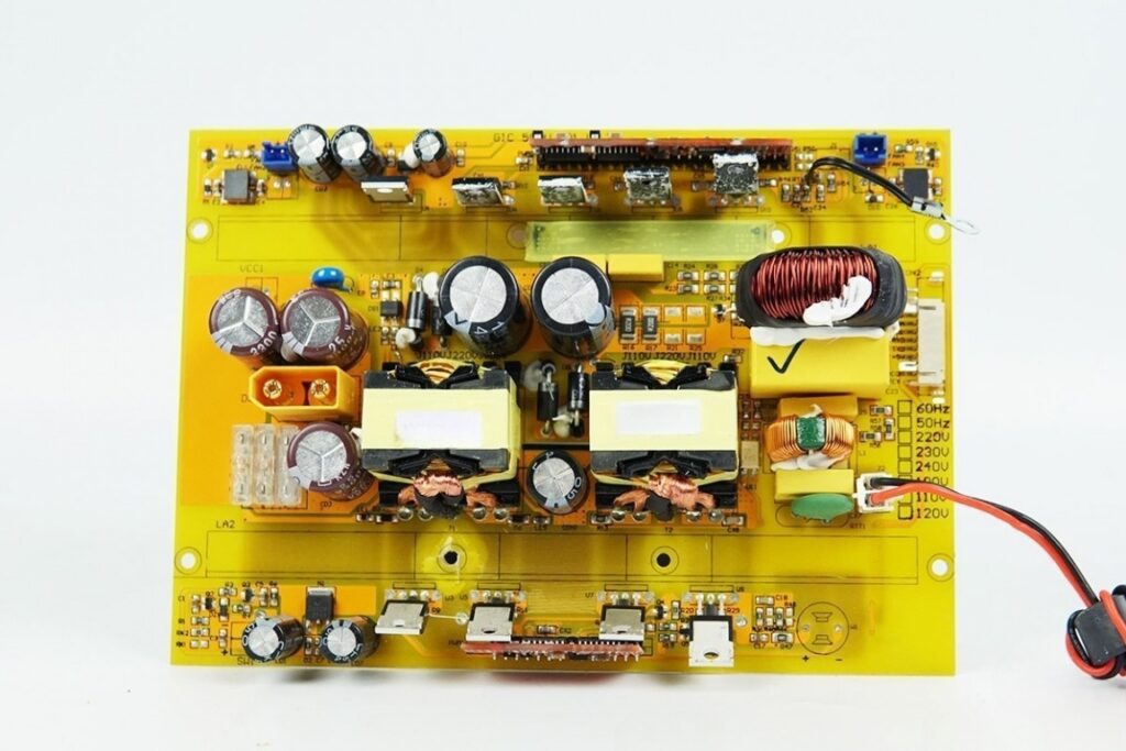
When developing hardware or power electronics, one of the most frustrating challenges I often face is dealing with EMC (Electromagnetic Compatibility) issues. These problems aren’t just technical hurdles—they can delay product launches, inflate costs, and complicate certifications. And what’s surprising is how often the root of the issue lies in a component many overlook: the transformer.
Transformers, especially in high-frequency applications, can act like miniature antennas—emitting or picking up unwanted electromagnetic interference (EMI) that disrupts surrounding systems. This interference isn’t just theoretical; it’s a real threat in industries where reliability is non-negotiable—like medical devices, industrial automation, and smart metering.
That’s why, in this blog, I want to share practical, field-tested techniques I use to reduce EMC interference during transformer design. Whether you’re building control systems or precision instruments, understanding these methods can save you countless hours of troubleshooting down the line.
Physical Mechanisms of EMC Interference
1.Magnetic Field Coupling
Transformers inherently generate high-frequency currents during operation, which can act as antennas, radiating electromagnetic fields. These fields can couple with nearby components through PCB traces, leading to EMI issues. Understanding this mechanism is crucial for designing effective shielding strategies.
2.Capacitive Coupling Paths
Inter-winding capacitance between the primary and secondary windings of a transformer can transmit noise signals. When the secondary is grounded, these signals often form a common-mode noise loop, which can propagate back through the PCB and affect other components. This highlights the importance of managing inter-winding capacitance and grounding strategies.
3.Voltage Instability Effects
Leakage inductance in transformers can cause spike voltages, particularly during switching operations. These voltage spikes can lead to unstable winding potentials, generating electric field interference. Reducing leakage inductance and stabilizing voltages are essential for minimizing EMI.

Why Are Transformers Prone to EMC Interference?
Transformers are prone to Electromagnetic Compatibility (EMC) interference due to their inherent design characteristics and operational dynamics. Below is a detailed breakdown of the key factors contributing to their susceptibility, supported by insights from industry research and standards:
1.High-Frequency Operation
Transformers in modern power electronics (e.g., switch-mode power supplies) operate at high frequencies (tens of kHz to hundreds of MHz). These frequencies amplify electromagnetic field radiation, allowing noise to propagate more easily into the surrounding environment. For example:
High-frequency switching generates rapid changes in current and voltage, creating harmonic interference and enabling the transformer to act as an unintended antenna.
This radiation can couple with nearby PCB traces or cables, leading to conducted or radiated emissions.
2.Parasitic Capacitances
The interwinding capacitance between primary and secondary windings is a critical source of common-mode (CM) noise:
Parasitic capacitances allow high-frequency noise to bypass the transformer’s isolation barrier, coupling noise from primary to secondary windings.
In isolated DC-DC converters, this capacitance becomes a dominant path for CM noise, especially in planar transformers where controlling capacitance is challenging.
Solutions include electrostatic shielding (e.g., Faraday shields) to redirect noise currents to ground.
3.Magnetic Material Behavior
Magnetic cores (e.g., ferrite) contribute to EMI through hysteresis and eddy currents:
During magnetization/demagnetization cycles, core materials generate fluctuating magnetic fields, which radiate noise.
High-permeability materials can exacerbate EMI if not properly shielded.
4.Switching Dynamics
Transformers in switching power supplies face voltage spikes and transients:
Rapid switching operations (e.g., MOSFET/IGBT transitions) produce broadband RF noise (up to 50+ MHz).
These spikes stem from parasitic capacitances discharging during switching, creating high-frequency harmonics that propagate as EMI.
5.Electromagnetic Field Radiation
Transformers inherently generate directional EM fields, which can:
Act as radiated emissions if unshielded, affecting nearby components.
Propagate noise via PCB traces or cables, turning them into unintended antennas.
6.Design and Layout Challenges
Proximity of Windings: Tight winding layouts improve coupling but increase interwinding capacitance, raising CM noise.
Grounding Issues: Poor grounding creates loops that amplify conducted emissions.
Transformers are inherently prone to EMC issues due to their high-frequency operation, parasitic elements, and electromagnetic field generation. Addressing these challenges requires a combination of shielding, material innovation, and layout optimization, guided by rigorous testing to meet industry standards. By integrating these strategies, engineers can minimize EMI, ensuring reliable performance in sensitive environments like medical devices and aerospace systems.
Key Design Element Comparison
| Design Element | Traditional Approach | Innovative Approach | Performance Gain |
| Shielding Structure | Single-layer copper foil | Double-layer orthogonal foil | 30–40% |
| Grounding Method | Direct grounding | Pre-stage negative connection | 50% |
| Winding Layout | Primary-Secondary-Auxiliary | Phase-balanced winding | 25% |
| Shielding Material | Standard copper foil | Nanocrystalline alloy | 20°C temp drop |
| Insulation | PVC sleeves | Triple-insulated wire | +30% voltage resistance |
Practical Design Techniques to Reduce EMC Interference
Have you ever wondered why EMC interference issues frequently trouble transformer designs, especially in high-power electronics?
Let’s explore some practical design techniques to effectively reduce EMC interference in transformers, backed by industry insights and standard practices.
The main challenges in transformer EMC design typically involve managing electromagnetic noise propagation, grounding inefficiencies, and material choices. Here’s six how you can tackle these effectively:
1.Shielding Techniques
Faraday Shields: Use copper foil or similar conductive materials to enclose windings, diverting noise currents to ground and reducing common-mode (CM) noise. Shields should be connected to the non-driven side of windings to enhance isolation.
Magnetic Shielding Enclosures: Surround transformers with enclosures made from materials like steel or mu-metal to capture stray magnetic flux and channel it to a ground plane. This approach is effective but adds cost and complexity.

2.Optimized Winding Layouts
Interleaving Windings: Interleave primary and secondary windings to reduce interwinding capacitance, minimizing CM noise. This technique requires careful design to ensure proper insulation and avoid short circuits.
Phase-Balanced Windings: Implement phase-balanced designs to cancel differential-mode noise, ensuring that each phase’s magnetic field is symmetrical.
3.Grounding Strategies
Single-Point Grounding: Ensure that all grounds converge at a single point to avoid creating ground loops, which can exacerbate EMI issues.
Shielded Grounding: Connect shields to a reliable grounding system to dissipate accumulated electromagnetic energy effectively.
4.Material Selection and Design
Low-Parasitic Materials: Use materials with low interwinding capacitance and leakage inductance to reduce parasitic effects. Smaller transformers generally have fewer parasitics.
Core Selection: Choose core geometries like toroidal or pot cores, which naturally contain EM fields better than EI or E cores.
5.Filtering and Encapsulation
EMI Filters: Implement filters at the input and output stages to suppress high-frequency noise. Single-stage filters can be effective with optimized transformer designs.
Encapsulation: Combine shielding with encapsulation to dampen vibrations and block EM fields, ensuring comprehensive protection.
6.Testing and Validation
Near-Field Probing: Use near-field probes to visualize magnetic flux near components, optimizing filter design and layout for better high-frequency performance.
Shielding Effectiveness Testing: Conduct thorough testing using EMI test chambers to ensure compliance with industry standards.
These techniques help mitigate EMC interference by addressing the root causes of noise generation and propagation in transformers. By integrating these strategies, engineers can enhance the reliability and performance of electronic systems while meeting stringent regulatory requirements.

Case Studies and Applications
Here are some case studies and applications related to reducing EMC interference in transformers:
1.Electronic Ballast Case Study
In a case study by Astrodyne TDI, an electronic ballast supplier changed a component without notifying customers, leading to significantly higher EMI emissions. To resolve this, Astrodyne proposed integrating an electronic ballast with an EMI filter into a single package, ensuring compliance and reducing interference.
2.Shielded Transformers in Critical Applications
Shielded transformers are particularly beneficial in applications where signal integrity is crucial, such as in medical devices and communication systems. They reduce electromagnetic interference (EMI) and radio frequency interference (RFI), ensuring clean and stable power delivery to sensitive electronic circuits.
3.EMI Elimination in Industrial Settings
In an industrial setting, multiple ASDs (Adjustable Speed Drives) were identified as sources of interference affecting a partial discharge test system. The solution involved installing filters at the ASDs to control both radiated and conducted emissions, ensuring proper installation to avoid impedance issues with long cable runs.
4.Isolated DC-DC Converter Solution
A case study on an isolated DC-DC converter highlighted the importance of identifying and addressing radiated emissions early in the design stage. Disabling components and analyzing emissions helped pinpoint the source of interference, leading to effective solutions like adding ferrite beads on power lines.
5.Robotics and Automation
In robotics and automation, EMI noise can significantly impact performance reliability. A case study demonstrated how addressing EMI issues improved electrical efficiency and power quality, emphasizing the need for robust EMC design strategies in these systems.
6.Active EMI Filtering in SMPS
Active EMI filtering techniques have been applied in Switch-Mode Power Supplies (SMPS) to reduce interference effectively. By using active components, the size and cost of passive filters can be significantly reduced while maintaining compliance with EMI standards like CISPR 25.
These case studies illustrate the importance of addressing EMC issues in transformer design across various industries, from industrial automation to medical devices, ensuring reliable performance and compliance with regulatory standards.
Conclusion:
In my experience, the best way to deal with EMC interference is not through last-minute fixes but by planning for EMC early in the transformer design process. The sooner we consider electromagnetic compatibility, the fewer issues we face later on, and the more stable and reliable the final product becomes.
That’s why I always encourage working with experienced manufacturers like Unicreed. We understand the unique EMC requirements across different industries, whether it’s for medical devices, industrial systems, or smart meters. Our goal is to help you achieve fast compliance and strong long-term performance.
If you are currently facing EMC challenges or planning a new project that needs high-quality transformers, feel free to contact me. You can email me at sales@unicreed-transformer.com or visit our website at www.unicreed-transformer.com. We offer custom samples and are happy to support your project needs.


