
High-frequency transformers are the heartbeat of today’s electronic systems. Whether it’s powering medical devices, smart meters, or industrial control systems, these compact components are essential for efficient energy transfer and signal integrity. But here’s the problem. As frequencies rise, two invisible challenges quietly begin to erode performance: the skin effect and the proximity effect. These phenomena increase AC resistance, cause unnecessary heat, and reduce overall efficiency.
I’ve seen how these effects can silently sabotage even the most well-designed systems. They lead to overheating, energy loss, and costly failures. That’s why it’s crucial to understand and actively mitigate them.
In this blog, I’ll show you how to reduce these losses through smarter design, better materials, and proven techniques. This will help your transformers run cooler, last longer, and perform better in demanding applications. If high efficiency and long-term reliability matter to you, this is a must-read.
What Are Skin and Proximity Effects?
Before we dive into how to reduce skin and proximity effects, it’s important to understand what these phenomena actually are and why they matter so much in high-frequency transformer design. These two effects are electromagnetic in nature, and while they might seem small on paper, they can create big problems in real-world applications. Let me break them down for you.
Skin Effect
When alternating current (AC) flows through a conductor, especially at high frequencies, it doesn’t distribute evenly across the wire’s cross-section. Instead, the current tends to concentrate near the surface. This is known as the skin effect. As the frequency increases, this effect becomes more severe, reducing the effective area for conduction. The result is higher AC resistance, increased heat generation, and more energy loss.
This is a critical issue in high-frequency transformers where every bit of efficiency matters, especially in compact and thermally sensitive systems like smart meters or medical power supplies.
Proximity Effect
The proximity effect happens when alternating currents in nearby conductors create magnetic fields that interfere with each other. These fields distort the current paths, causing the current to flow unevenly, often crowding one side of the conductor. The closer the conductors and the higher the frequency, the more severe the impact.
This leads to additional copper losses and the creation of hot spots, which can damage insulation and reduce transformer lifespan.
Real-World Consequences
In practical terms, skin and proximity effects lead to:
- Increased operating temperatures
- Lower energy efficiency
- Risk of premature transformer failure
- Higher operational costs and maintenance needs
That’s why addressing these effects is not just about better performance. It’s essential for product reliability, safety, and long-term value.
Why skin & proximity effects hurt transformers more than people expect?
Before we dive into how to reduce these effects, it’s important to understand why skin and proximity effects are more damaging than many engineers initially expect. These losses often go unnoticed during early design phases but can quietly degrade performance, efficiency, and thermal stability in real-world operation. Let me explain what they do and how they show up in your final product.
What They Do
Skin Effect: At high frequencies, current naturally shifts toward the outer surface of a conductor. This reduces the effective cross-sectional area available for current flow, which increases the AC resistance. The higher the frequency, the more pronounced the effect becomes.
Proximity Effect: Often even more harmful, this occurs when magnetic fields from nearby windings force the current to crowd into small regions within the conductor. This uneven distribution causes localized heating and higher copper losses.
What You See in Real Products
- Hot Windings with a Cool Core: You might measure a transformer and find the core is operating at a safe temperature, but the windings are unexpectedly hot. This is a clear sign of skin and proximity losses.
- Efficiency Drops at High Load: As current increases, so do the localized effects of proximity and skin loss. This leads to non-linear efficiency behavior—performance that looks fine at low load but degrades quickly as demand increases.
- Local Hot Spots: Especially near winding window edges or in the first few layers of winding. These hot spots can cause insulation breakdown or premature failure even if the rest of the transformer seems thermally stable.
In my experience, many failures happen because designers calculate DC copper loss only, then wonder why winding temperature rise is 20–40°C higher in the prototype.
When designing high-frequency transformers, managing skin and proximity effects isn’t just about choosing the right wire or adding insulation. It requires a deeper understanding of how current behaves, how magnetic fields interact with conductors, and how your design choices influence losses. Many times, engineers focus on obvious issues like core saturation or temperature rise, but overlook how these electromagnetic effects quietly reduce efficiency and create hidden thermal stress.
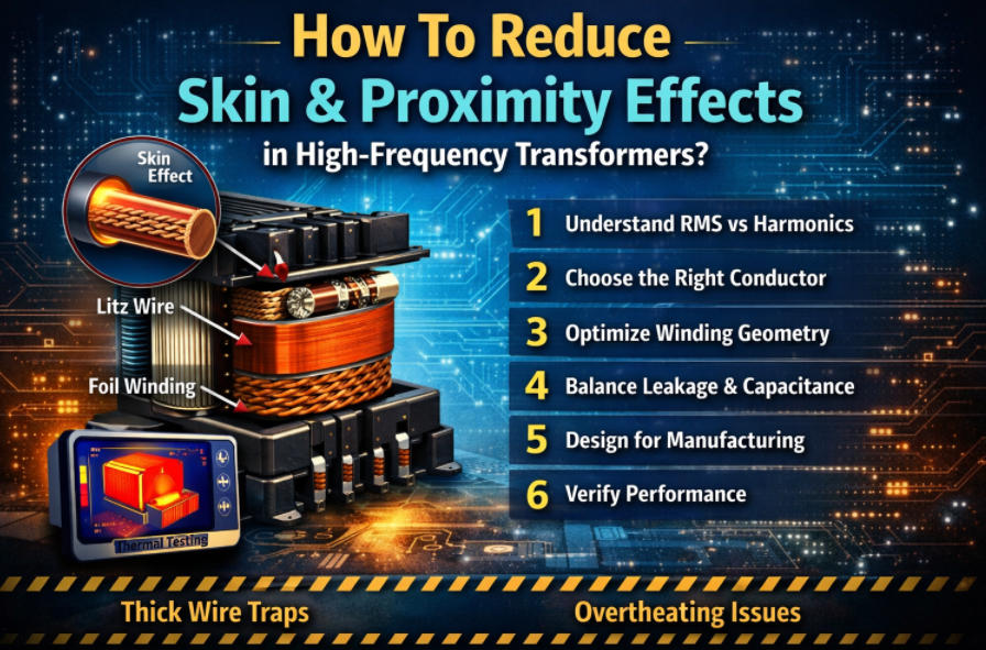
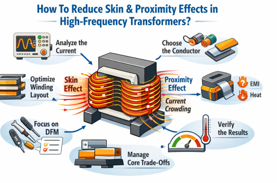
To help you avoid common pitfalls and improve both performance and reliability, here are six practical tips I use when designing transformers at Unicreed:
- Step 1, Don’t optimize the wrong current: RMS, harmonics, and waveform
- Step 2, Choose the right conductor: solid vs stranded vs Litz vs foil
- Step 3, Winding geometry: the #1 lever for proximity-effect reduction
- Step 4, Core/winding arrangement trade-offs: leakage, capacitance, EMI, and temperature
- Step 5,Practical design tactics we use during DFM (design for manufacturing)
- Step 6, How to verify you actually reduced skin/proximity losses (not just “feel cooler”)
Step 1, Don’t optimize the wrong current: RMS, harmonics, and waveform
Let’s start with the foundation: understanding the actual current flowing through your transformer. Many engineers make the mistake of designing around average or DC current values. But when it comes to skin and proximity effects, it’s the high-frequency AC components, especially harmonics, that do the damage. Optimizing for the wrong current type can lead to unnecessary losses and missed efficiency targets.
Step 1: Don’t Optimize the Wrong Current
Skin and proximity losses are not driven by average or even total RMS current alone. They are mostly caused by the high-frequency content within your current waveform. This means harmonics and ripple shape play a huge role in how the losses show up.
Here’s what you need to calculate and collect before making design choices:
- Primary and Secondary RMS Current: Start with accurate RMS values under typical and worst-case loads.
- Ripple Current Shape: Is your current triangular, discontinuous, or sinusoidal? Each affects conductor losses differently.
- Duty Cycle and Peak Current: These influence harmonic content and effective AC resistance.
- Harmonic Analysis: Use FFT tools or simulation data to understand how much high-frequency energy is in your signal.
In my experience, rectifier + capacitor outputs and peaky currents can push copper loss much higher than “V×I” intuition suggests (even in low-frequency transformers, catalog notes warn about this effect).
Step 2, Choose the right conductor: solid vs stranded vs Litz vs foil
Once you understand the current waveform, the next step is to choose the right conductor for your application. The conductor type directly affects how much skin and proximity losses you’ll face, especially at higher frequencies. Many failures in high-frequency transformers are caused not by poor design intent, but by poor material choices or overlooked production challenges. Let me break down the options we commonly use and what you need to watch out for.
Step 2: Choose the Right Conductor
Solid Round Wire
This is the most common and cost-effective option. It works well at lower frequencies, with small diameters, or in single-layer windings where skin effect is minimal. But it quickly becomes inefficient in high-frequency, high-current applications, especially when used in large diameters or multi-layer coils. Skin and proximity effects here can be severe.
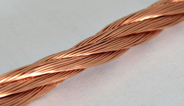
Litz Wire
Litz wire solves the skin effect problem by using many individually insulated strands woven in a specific pattern. If the strand diameter is chosen properly, it ensures uniform current distribution and reduces AC resistance. However, Litz wire has practical drawbacks. It’s more expensive, less available in some regions, and more difficult to terminate cleanly. In our factory, we see most Litz-related failures at the termination points, caused by poor solder wetting, strand damage, or incomplete resin impregnation.
Copper Foil
Foil windings are excellent for high-current and low-profile designs. They allow precise layer geometry and controlled winding layout. But they are not immune to proximity losses. If layers are tightly stacked without spacing or interleaving, the magnetic fields between layers can create severe localized losses. Also, in production, foil requires extra care. We pay close attention to edge insulation and burr control to avoid partial discharge and ensure long-term reliability.
Rectangular Wire and Multi-Strand Bunched Wire
These are good middle-ground solutions. Rectangular wire offers better packing density and reduced proximity effect compared to round wire. Multi-strand bunched wire can help distribute current more evenly but may not match the performance of true Litz. Both options involve trade-offs in winding complexity and manufacturing consistency.
Choosing the right conductor isn’t just about specs. It’s also about what you can build consistently and reliably. At Unicreed, we evaluate conductor types not only by performance but also by production quality and long-term durability.
Step 3, Winding geometry: the #1 lever for proximity-effect reduction
After choosing the right conductor, the next and often most powerful tool I use to reduce proximity effect is winding geometry. Unlike skin effect, which is tied to frequency and conductor type, proximity effect is mainly driven by the magnetic fields created by neighboring turns and layers. That means the physical layout of your windings matters a lot. Get the geometry right, and you can dramatically reduce AC resistance and hot spots without changing materials or increasing cost.
Step 3: Winding Geometry – The Number One Lever for Proximity-Effect Reduction
Minimize Layer Count
Whenever possible, I aim for a single-layer winding. This alone eliminates much of the inter-turn coupling that causes proximity losses. If more layers are needed, I try to distribute them evenly with spacing between layers.
Controlled Spacing and Distributed Gaps
Using part of the winding window as a gap, often called a controlled fill strategy, spreads out the turns and reduces the intensity of the magnetic fields between them. This lowers the proximity losses significantly.
Interleaving Primary and Secondary Windings
Interleaving can reduce leakage inductance, which is beneficial for high-frequency switching. But I always warn designers to be careful. Too much interleaving can increase AC resistance in the inner layers, especially with foil or solid wire. I have seen units fail thermal tests on our production line because of this issue.
Sectional Bobbins
These help isolate high-field regions. By separating windings into sections, you reduce the overlapping of magnetic fields and the resulting proximity effects.
Foil Sandwich Structures
For high-current designs, I sometimes use a foil sandwich layout. This includes insulation and spacing between foil layers to balance the magnetic field distribution. When done correctly, it can be very effective, but it does require precision in design and manufacturing.
Winding geometry is more than just fitting turns in a bobbin. It is a key part of managing magnetic fields. Smart geometry helps your transformer run cooler, last longer, and perform more reliably and that is always a priority in Unicreed designs.
Step 4, Core/winding arrangement trade-offs: leakage, capacitance, EMI, and temperature
After adjusting winding geometry to control proximity losses, the next challenge is balancing trade-offs between leakage inductance, interwinding capacitance, EMI, and thermal performance. These factors are all linked through your core and winding arrangement. You cannot optimize everything at once, so it’s important to understand the trade-offs and make deliberate choices based on your application goals. Here’s how I approach it.
Interleaving vs. Capacitance
Interleaving windings, where primary and secondary layers alternate, helps reduce leakage inductance. This improves energy transfer and benefits fast-switching converters. However, more interleaving also increases interwinding capacitance, which can create serious EMI and common-mode noise issues.
This is a common design trap. You improve leakage performance, but then fail EMC testing due to excess high-frequency coupling.
Window Utilization vs. Thermal Performance
Maximizing fill factor is often seen as good transformer design. But at high frequencies, too much copper packed into the window can lead to serious thermal challenges. With skin and proximity effects already raising AC resistance, poor airflow and reduced heat dissipation only make things worse.
In some cases, less copper and more space actually improves long-term reliability by lowering winding temperature.
Making the Right Trade-Offs
From my experience, the best designs make clear choices based on the final application. Instead of chasing every spec, choose your priority: better efficiency, lower EMI, or cooler operation. Then structure your core and winding to support that goal.
Design Decision Table
| If Your Priority Is… | Then Use This Strategy |
| Lower leakage inductance | Moderate interleaving plus optimized conductor placement |
| Lower EMI or common-mode noise | Sectional bobbin plus shielding and reduced layer overlap |
| Cooler thermal performance | Lower fill factor plus spacing and improved core ventilation |
| Balanced performance | Selective interleaving and tuned insulation layout |
Every transformer involves trade-offs. The key is knowing which performance aspects matter most to your system. In the next step, I will explain the practical techniques we apply during DFM to ensure these design goals survive real-world manufacturing.
Step 5,Practical design tactics we use during DFM (design for manufacturing)
Even the best transformer design can fail in production if it’s not built with manufacturing realities in mind. That’s why design for manufacturing, or DFM, is a key part of our process at Unicreed. DFM ensures that performance on paper translates to consistent, high-quality results on the production floor. Reducing skin and proximity effects is not just about materials and layout. It also depends heavily on how the transformer is physically assembled and finished. Here are the practical tactics we apply during manufacturing.
Step 5: Practical Design Tactics We Use During DFM
Termination and Soldering
Litz wire is excellent for performance, but its many fine strands make termination a challenge. We take extra care to prevent strand damage, ensure even solder wetting, and apply proper strain relief to avoid fatigue failure. In some cases, crimping or ultrasonic welding is more reliable than soldering. A poor termination can negate the benefits of Litz by introducing resistance or thermal hotspots.
Insulation System
Choosing the right insulation materials and layout is critical. We select tapes with the right thermal and dielectric properties, and we always maintain proper insulation margins. For safety and long creepage requirements, we use triple-insulated wire when appropriate. These small details make a big difference in long-term reliability, especially in high-frequency and high-voltage designs.
Impregnation and Potting
Varnish or potting resin helps stabilize windings, improve thermal transfer, and protect against vibration. However, it also makes rework more difficult and may affect capacitance. We carefully select potting materials that match the thermal needs of the application and ensure even penetration to avoid voids. Consistent potting also prevents partial discharge and moisture ingress over time.
By applying these DFM practices, we not only reduce electrical losses but also improve mechanical integrity and product lifespan. At Unicreed, every design is reviewed with both performance and manufacturability in mind because a transformer that’s hard to build is a transformer that won’t deliver consistent results.
Step 6, How to verify you actually reduced skin/proximity losses (not just “feel cooler”)
After all the effort you’ve put into conductor selection, winding geometry, and DFM tactics, the final step is proving your improvements actually worked. It’s not enough to say, “The unit feels cooler” or “It seems okay at light load.” You need real measurements to confirm that skin and proximity losses have been minimized especially under full operating conditions. Here’s how we validate it during prototyping and testing.
Step 6: How to Verify You Actually Reduced Skin/Proximity Losses
What to Measure on Prototypes
Winding Temperature Rise
Run the transformer at rated load until it reaches thermal steady-state. Compare temperature rise across winding sections. Uneven or high temperatures may indicate localized AC losses.
Efficiency vs Load Curve
Plot efficiency at 25%, 50%, 75%, and 100% load. A sudden drop at high load is a classic sign of rising AC losses from skin and proximity effects.
AC Resistance Estimation
If you have access to impedance analyzers or frequency sweep tools, measure winding resistance over frequency. This helps separate DC resistance (Rdc) from frequency-dependent AC resistance (Rac).
Hot-Spot Mapping
Use thermocouples or infrared imaging to identify hot spots. Be cautious: IR only sees the surface, and potting or airflow can mask deeper issues.
Common Failure Patterns We See
- “Works fine at 50% load, fails at full load”
- This usually points to proximity effect issues, where RMS current is within spec but local Rac spikes under full field conditions.
- “Only one side runs hot”
- This often indicates asymmetric winding or termination issues, where one side has higher contact resistance or poor soldering.
At Unicreed, we treat testing as part of the design not an afterthought. If you’re not verifying the right parameters, you could miss hidden loss mechanisms that shorten lifespan or cause early failures.
What Are Common mistakes In Real-world Failure Modes?
Even with the best intentions, high-frequency transformer designs often run into problems during testing or field operation. From what I’ve seen on the production line and in customer feedback, many of these failures come from a few common mistakes that are easy to overlook during early design. Spotting them quickly can save time, cost, and performance loss. Here are 4 real-world pitfalls you should watch out for.
Common Mistakes in Real-World Failure Modes
1.Using Thick Solid Wire Because “DC Loss is Low”
This is one of the most common traps. Designers focus on DC resistance and choose thick solid wire to reduce I²R losses. But at high frequencies, skin effect makes only the outer surface of the wire conduct current. The inner copper becomes wasted mass, while AC resistance skyrockets.
2.Packing in Too Many Layers to “Fit Turns”
Trying to squeeze all turns into a tight winding window often leads to multiple winding layers. The inner layers end up buried under stronger magnetic fields and poor cooling paths, causing local overheating and reliability problems. More layers might solve your voltage or turns ratio problem, but they often break your thermal and efficiency goals.
3.Aggressive Interleaving Without Checking Rac and Capacitance
Interleaving helps reduce leakage inductance, but if overused, it increases proximity effect and interwinding capacitance. Both can cause higher AC losses and worsen EMI. Always simulate or measure AC resistance (Rac) and check common-mode noise performance before locking in an aggressive winding layout.
4.Ignoring Termination Losses
Contact resistance at terminations can be small on paper, but in high-current, high-frequency systems, even a few milliohms can generate serious heat. Poor soldering, strand damage in Litz wire, or uneven crimp pressure are all culprits. These issues often show up as local hot spots near terminals.
Quick Debug Tip from My Experience
If you’re debugging a high-frequency transformer that runs hot, the fastest check is to compare your measured copper temperature rise against the expected rise from calculated DC copper loss. If there’s a big mismatch, proximity loss or termination problems are usually the cause.
At Unicreed, we’ve learned to design with both simulation and practical testing in mind. Avoiding these common mistakes is key to building transformers that work not just in theory, but in the real world.
Case Study: Reducing Skin & Proximity Effects in a 100 kHz, 300 W Transformer
Design Targets
- Frequency: 100 kHz
- Power: 300 W
- Efficiency: at least 95%
- Temperature rise: no more than 30°C
Baseline Design
- Primary: single solid copper wire, 0.6 mm diameter
- Secondary: triple insulated wire
- Winding: sequential winding with primary and secondary wound in the same direction
Main Problems
- Skin effect increased the primary AC resistance because 0.6 mm is larger than twice the skin depth at 100 kHz.
- Proximity effect caused strong current crowding between layers. The middle layer current density reached about 1.8 times the surface value, and the loss share exceeded 40 percent in the hotspot area.
Improvements
- Split the primary into two parts and place the secondary in the middle to form a Primary Secondary Primary sandwich layout. This reduced proximity effect and lowered the middle layer current density to about 1.2 times the surface value.
- Change the primary to 0.1 mm times 40 strands. The total copper area stayed close to the original, but each strand was smaller than the skin depth range, so skin effect was strongly reduced.
- Use 0.3 mm times 7 strands triple insulated wire on the secondary. Individual insulation helps suppress circulating currents and improves current sharing.
- Add high temperature insulation tape between primary layers to meet the 1500 V insulation requirement and stabilize the winding structure.
- Apply vacuum impregnation so varnish fills voids and improves insulation consistency.
Results
- Full load efficiency reached 96.5%.
- After 2 hours at full load, core and winding temperature rise was about 25°C.
Takeaway
At high frequency, lower loss comes mainly from lower AC resistance. Fine strand conductors and a well balanced winding layout are practical ways to reduce skin and proximity effects.
FAQ
Q1:Is Litz always better than foil?
A:Not always. Litz wire is excellent for reducing skin and proximity effects in high-frequency, low to medium current applications. But for high-current or low-profile designs, copper foil may perform better in terms of packing efficiency and thermal management. The best choice depends on your frequency, current, and space constraints.
Q2: At what frequency does solid wire become a problem?
A:Solid wire typically becomes inefficient when your operating frequency exceeds 100 kHz, especially if the wire diameter is large. Skin effect significantly raises AC resistance beyond this point. For anything above that, consider Litz wire or alternate geometries.
Q3:Does tighter coupling always improve efficiency?
A:No. While tighter magnetic coupling can reduce leakage inductance, it often increases interwinding capacitance, which may lead to EMI or common-mode noise issues. Efficiency gains must be weighed against potential losses elsewhere in the system.
Q4: Why did my transformer get hotter after reducing leakage inductance?
A:You may have introduced more interleaving, which can increase proximity effect losses, especially in the inner layers. It’s a common trade-off: lower leakage inductance can unintentionally raise AC resistance, making windings hotter despite a better coupling factor.
Q5:How do I measure proximity effect losses without complex tools?
A:Start by comparing your measured copper temperature rise with the calculated DC copper loss. If the actual temperature is much higher than expected, and the core remains cool, it’s a strong sign of proximity or skin effect losses. Thermal imaging and basic AC resistance tests at different frequencies can also provide clues.
Conclusion
Skin and proximity effects are more than just technical side notes. They are real challenges that directly impact the efficiency, heat management, and reliability of high-frequency transformers. As frequency increases, the need to address these losses becomes even more critical.
At Unicreed, I work closely with engineers and manufacturers like you to deliver high-frequency transformers that are not only efficient but also built to last. With our deep experience, high-quality materials, and 100% tested production, we help you reduce losses and meet demanding application requirements.
If you’re looking for reliable, high-performance transformer solutions tailored to your specific needs, contact me at Unicreed today. Let’s power your next innovation with smarter efficiency.
Related Blog:
- How To Choose Copper Wire Diameter For High Frequency Transformer?
- What Are The Different Types Of Winding Arrangements Used In High Frequency Transformers
- How to Improve Working Efficiency of High Frequency Transformer
- What Practical Techniques Can Reduce EMC Interference in Transformer Design?
- Everything You Need to Know High-Frequency Transformer Flying Leads Wire
