
Powering everything from industrial systems to cutting-edge appliances, high-frequency transformers are vital to modern technology. Their ability to efficiently transfer energy is unmatched, but even the most advanced transformers must meet strict safety and quality standards to perform reliably.
That’s where HI-POT (High Potential) testing comes in. This critical test ensures the insulation system can handle high voltage safely, protecting devices from breakdowns and users from potential hazards. The stakes are high—pass the HI-POT test, and you have a dependable product. Fail it, and risks like electrical fires or costly repairs loom large.
The reality? Many transformers fail the test due to common issues such as damaged insulation, improper pin spacing, or material defects. If these challenges sound familiar, don’t worry—you’re in the right place. In this post, I’ll explore the root causes of poor HI-POT performance and guide you toward practical, effective solutions.
Understanding HI-POT Performance
Have you ever wondered why some high-frequency transformers fail during HI-POT testing?
This is why understanding the HI-POT performance is crucial for ensuring the reliability and safety of transformers in various applications.
The HI-POT test measures the dielectric strength of a transformer’s insulation. During this test, a high voltage is applied between the windings or between the winding and the core. The main objectives of this process include:
- Ensuring that the transformer’s insulation can withstand potential surges or faults without failing.
- Identifying weaknesses in insulation that could lead to dangerous outcomes, such as electrical fires or device malfunctions.
Failures in HI-POT performance often highlight specific design or manufacturing issues that need to be addressed to enhance overall transformer reliability.

Common Causes of HI-POT Failures
Do you know how even minor design flaws can cause high-frequency transformers to fail the critical HI-POT test? Despite rigorous testing, many manufacturers encounter persistent issues that compromise insulation integrity.
Let’s explore the most common challenges that lead to poor HI-POT performance and understand their impact on transformer reliability.
The main challenges contributing to HI-POT failures include:
| Cause | Effect | Root Cause |
| Inadequate Pin Spacing | Voltage creepage or arcing occurs, leading to insulation breakdown. | Poor design standards, outdated layouts, or non-compliance with IEC or UL guidelines. |
| Damaged Enameled Wires | Tiny nicks or abrasions expose copper, causing short circuits under high voltage. | Mishandling during winding, insufficient tension control, or substandard wire materials. |
| Overheating of Triple-Insulated Wires | Melting insulation layers compromise dielectric strength. | Improper soldering techniques, lack of thermal management, or inadequate tools. |
| Cracks in the Bobbin | Exposed windings or misaligned layers lead to arcing during testing. | Low-quality plastics, improper handling, or excessive stress during assembly. |
| Tears in Insulation Tape | Compromised insulation allows high voltage to penetrate unintended areas. | Poor tape application, sharp tools during production, or inconsistent material quality. |
| Issues with Reverse-Folded Tape | Gaps or overlaps reduce insulation effectiveness. | Lack of worker training or errors in high-speed automation processes. |
| Poor Adhesive Application | Insufficient adhesive can cause insulation material to peel or shift under high voltage. | Faulty adhesive dispensers or suboptimal application parameters. |
How to Enhance HI-POT Performance
Have you ever wondered why some transformers perform flawlessly in HI-POT testing while others fail repeatedly, even with the same manufacturing setup? The secret lies in the small but crucial details in design, materials, and processes.
This is why enhancing HI-POT performance is essential for the reliability and safety of these transformers.
This process involves:
1.Optimizing Transformer Design
- Increase pin spacing to comply with or exceed IEC and UL safety standards.
- Use high-quality, heat-resistant bobbins to prevent cracks and deformation.
- Add redundant insulation layers with extra tape or varnish for enhanced dielectric strength.
2.Upgrading Quality Control Processes
- Implement automated inspection systems to detect wire damage early.
- Introduce inline HI-POT testing to identify defects during production.
- Regularly audit tapes, adhesives, and other critical materials for quality.
3.Refining Manufacturing Techniques
- Train workers in proper soldering practices to prevent overheating of wires.
- Standardize insulation tape application for consistent coverage and tension.
- Use calibrated adhesive dispensers for uniform and reliable application.
4.Leveraging Advanced Materials
- Source enameled wires with high abrasion resistance for durability.
- Utilize triple-insulated wires with superior thermal ratings to handle higher stress.
- Test and select insulation tapes with exceptional dielectric properties.
5.Employing Advanced Testing Protocols
- Use dynamic HI-POT testing to replicate real-world transient voltage conditions.
- Perform thermal cycling tests to assess material performance under fluctuating temperatures.
- Adopt statistical process controls (SPC) for continuous defect monitoring and improvement.
Real-World Examples and Success Stories
Have you ever wondered how specific transformer designs can lead to successful HI-POT testing outcomes?
This is why examining real-world examples, such as the EE40 (9+9) PIN transformer, can provide valuable insights into effective HI-POT performance
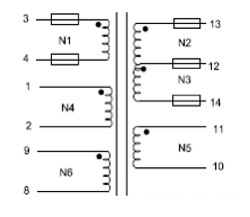
The EE40 (9+9) PIN transformer serves as an excellent case study for understanding HI-POT testing requirements:
Types of Voltage Testing
1.Winding-to-Winding Voltage
- Primary to primary voltage (e.g., N1 to N4, N1 to N6, N4 to N6).
- Secondary to secondary voltage (e.g., (N2 + N3) to N5).
- Primary to secondary voltage (e.g., (N1 + N4 + N6) to (N2 + N3 + N5)).
2.Winding-to-Core Voltage
- Primary windings (e.g., N1, N4, N6) to the core.
- Secondary windings (e.g., N2, N3, N5) to the core.
3.Testing Requirements:
- The primary-to-secondary voltage requirement is the highest, typically exceeding 3750VAC, and is tested using a HI-POT tester with adjustable dual fixtures.
- Other voltage tests are often conducted using point measurement methods, depending on application and process specifications, typically ranging from 1000 to 1750VAC.
- In some cases, probe fixtures are used for a one-time test of winding-to-winding voltage.
Through these specific testing requirements and successful case studies, it becomes clear that careful design and rigorous testing are crucial for ensuring HI-POT performance in high-frequency transformers. These practical experiences provide valuable references for the industry, helping to enhance the safety and reliability of future products.
Conclusion:
HI-POT testing is not just a quality assurance step it’s a critical safeguard for ensuring the safety and reliability of high-frequency transformers. By identifying weaknesses in insulation, HI-POT testing protects devices, prevents costly failures, and ensures compliance with industry standards.
Improving HI-POT performance requires adopting best practices, from optimizing design and materials to implementing rigorous quality control. These steps enhance both safety and reliability, giving you and your customers confidence in every transformer you produce.
At Unicreed, we specialize in tailored solutions for high-frequency transformers. Whether you’re facing specific challenges with HI-POT performance or looking to elevate your manufacturing standards, we’re here to help. Contact us today to explore how our expertise can empower your business to produce safer, more reliable transformers that exceed expectations. Let’s build a brighter, more efficient future together.
