Many engineers assume that if a transformer is rated 12V or 24V, the load will receive exactly that voltage. However, in real projects this is often not the case. In my experience working with OEM equipment, engineers sometimes measure the transformer output on the bench and everything looks correct. But after the system is installed, the voltage measured at the load becomes noticeably lower.
This situation can be frustrating. The first reaction is often to suspect the transformer quality or design. In our factory, we frequently receive questions like this from customers who believe the transformer is not performing correctly.
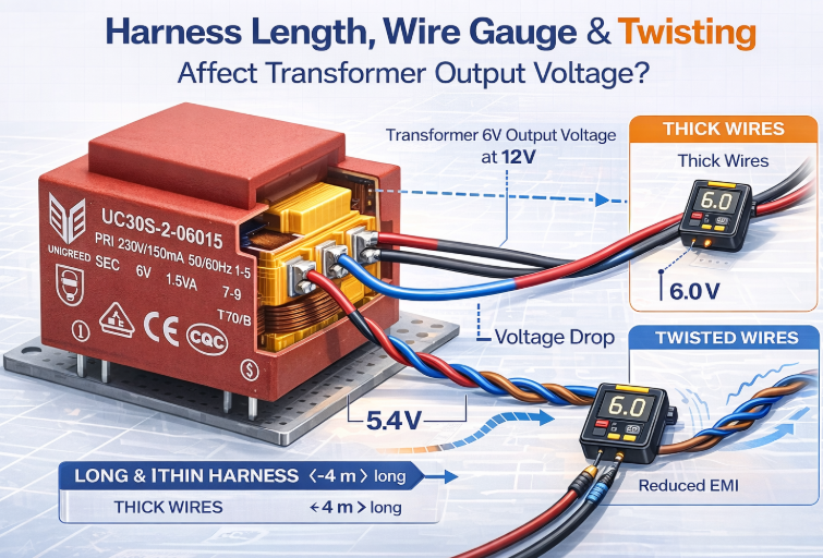
In many cases, the real cause is much simpler. Small wiring details such as harness length, wire gauge, and whether the wires are twisted can significantly influence the voltage that finally reaches the load. Understanding how these practical factors affect transformer output can help engineers avoid voltage drop problems and design more stable systems.
Why Transformer Output Voltage in Real Systems Often Differs from the Rated Value?
Before discussing harness length, wire gauge, and twisting, it is important to understand a common observation in real transformer applications: the voltage measured in the system often does not exactly match the rated secondary voltage on the transformer specification.
In my experience working with OEM equipment and industrial control cabinets, engineers sometimes assume that if a transformer is rated for 12 V or 24 V, the load will always receive that exact voltage. However, a transformer’s rated voltage is defined under specific test conditions, typically at the transformer terminals with nominal input voltage and rated load. Once the transformer is installed in real equipment, several external factors begin to influence the actual voltage delivered to the load.
In our factory, when customers report unexpected voltage differences, the transformer itself is not always the root cause. Very often, the wiring between the transformer and the load plays a critical role. Factors such as harness length, wire gauge, and wiring layout (including twisting) can introduce additional resistance or electromagnetic effects, which shift the voltage that finally reaches the load. Understanding these practical factors helps explain why transformer output voltageproper wire gauge can vary in real systems.
How Harness Length Influences Transformer Output Voltage
When discussing transformer performance, it is easy to focus on VA ratings, secondary voltage, and efficiency. But in real applications, the transformer is only one part of the power path. The wiring harness between the transformer and the load becomes part of the electrical circuit. In my experience supporting OEM customers, unexpected voltage drops at the load are often traced not to the transformer itself, but to the length of the harness connecting it. A longer harness introduces more resistance, and that resistance directly affects the voltage delivered to the load.
The core principle is simple:
Longer wire = higher resistance = more voltage drop under load.
Every conductor has a specific resistance per meter. As the harness becomes longer, the total resistance increases. When current flows through this resistance, part of the voltage is lost before it reaches the load (Vdrop = I × R). This effect becomes especially noticeable in low-voltage secondaries such as 6 V, 9 V, 12 V, or 24 V, because even a small voltage drop represents a large percentage of the output.
In our factory, we often see this issue in industrial control cabinets where transformers are mounted far from the load. Once the wiring extends several meters, the voltage at the load can fall below specification even though the transformer itself is performing correctly. This is why understanding and managing harness length is an important part of achieving stable voltage performance in real-world transformer applications.
Why Wire Gaug Directly Affects Transformer Voltage Stability?
Wire gauge plays a critical role in determining how stable the transformer output voltage will be once the system is operating under load. In practical terms, the wire gauge defines the cross-sectional area of the conductor, and that area determines the electrical resistance of the wire. Thicker wires have lower resistance, while thinner wires have higher resistance. This matters because any resistance in the wiring path creates a voltage drop when current flows through it.
In my experience working with OEM systems, voltage instability at the load is often caused by using a wire gauge that is too small for the required current. When the load draws higher current, the voltage drop across a thin conductor becomes more significant. As a result, the voltage that reaches the load can be several percent lower than what the transformer actually provides at its terminals. This effect is even more pronounced in low-voltage systems. For example, losing 0.5 V in a 24 V circuit is minor, but losing 0.5 V in a 6 V circuit represents a much larger percentage drop.
Another issue we frequently see in our factory is that engineers sometimes size wires based only on mechanical convenience or available space in the harness. However, if the wire gauge is too small, the conductor heats up and resistance increases further, causing even more voltage loss under sustained load. This can lead to fluctuating output voltage, equipment instability, and in more severe cases, reduced component lifespan.
To maintain stable transformer output voltage at the load, it is essential to select a wire gauge that matches both the current requirement and the harness length. Proper wire sizing ensures minimal resistance, reduces voltage drop, and keeps the system operating within the intended electrical specifications.
How Wire Twisting Influences Transformer Output Voltage?
Before diving into the technical details, it is helpful to understand that wire twisting does not change transformer voltage in the same way that harness length or wire gauge does. It does not add meaningful resistance, and it does not directly cause voltage drop. Instead, twisting influences the stability and cleanliness of the voltage by controlling electromagnetic behavior around the wiring. In my experience working with OEM applications, many engineers encounter voltage fluctuations or noise issues that are ultimately linked to wiring layout rather than the transformer itself. Twisting the wires becomes an important method to improve signal integrity and reduce interference, especially in environments with switching devices, motors, or power electronics.
Wire twisting matters because it reduces the loop area between conductors, which lowers the amount of electromagnetic interference that can couple into or out of the transformer wiring. When the wires are twisted, the electromagnetic fields generated by the current tend to cancel each other, resulting in less radiated noise and reduced susceptibility to external interference. This helps stabilize the voltage delivered to sensitive loads, particularly when dealing with low-level control signals or noisy industrial environments.
In our factory, we see twisted wiring used frequently in applications such as industrial control cabinets, sensors, and communication interfaces. When wires are not twisted and run in parallel for long distances, they can pick up noise from adjacent circuits. This does not reduce the average voltage, but it introduces fluctuations that can affect sensitive devices or feedback circuits. Twisting the wires mitigates these issues by ensuring that noise picked up along the wire is balanced and largely cancelled.
Although twisting does not replace proper wire sizing or harness length control, it is a valuable practice to enhance voltage stability and reduce EMI-related issues. For engineers working on transformer-powered systems, considering twisting as part of the wiring strategy can lead to more reliable and predictable voltage performance, especially in environments where noise is unavoidable.
What Are The Combined Effect of Harness Length, Wire Gauge, and Twisting?
Evaluating transformer performance in real equipment, it is important to recognize that these three wiring factors do not act independently. In my experience working with OEM systems, voltage deviations at the load often come from a combination of harness length, wire gauge, and wiring layout rather than a single cause. Even if each factor contributes only a small amount of resistance or noise on its own, the combined effect can become significant and lead to unstable or unexpectedly low voltage in the final application.
How Length and Wire Gauge Interact to Magnify Voltage Drop
Harness length and wire gauge work together to determine the total resistance of the wiring path. A long harness made with a small wire gauge creates a much larger voltage drop than either factor alone. In our factory, this is one of the most common causes of customers reporting lower-than-expected voltage at the load. Even a correctly designed transformer cannot compensate for excessive wiring resistance created by this combination.
How Twisting Helps Stabilize Voltage in Noisy Environments
Twisting the wires does not reduce resistance, but it significantly reduces electromagnetic interference. When long harnesses run near switching devices, motors, or high-current conductors, noise can couple into the transformer wiring. Twisting helps maintain stable voltage by minimizing induced voltage spikes and preventing fluctuations that can affect sensitive circuits. This is especially useful when the load includes sensors or control electronics.
Why Real-World Performance Depends on the Entire Wiring System
In our production support work, we often remind engineers that the transformer specification only defines performance at the transformer terminals. The actual voltage at the load is determined by the entire wiring system. When harness length, wire gauge, and twisting are not optimized together, the final system may operate outside the expected voltage range even if the transformer itself is perfectly designed.
What Are The Design Tips for Stable Transformer Output Voltage
Achieving stable transformer output voltage is not only about selecting the right transformer. In real equipment, the wiring between the transformer and the load becomes part of the electrical system, and its design directly affects the final voltage seen by the end device. In my experience supporting OEM customers, many voltage issues can be prevented simply by applying a few practical design rules during the early stages of the project. The goal is to minimize avoidable voltage drop, reduce noise, and ensure the transformer performs as intended under real load conditions.
Keep Harness Length as Short as Practical
Long wiring increases resistance and causes measurable voltage drop, especially in low-voltage applications such as 6 V, 9 V, 12 V, and 24 V.
To improve stability:
- Minimize the distance between the transformer and the load.
- Avoid routing the harness through unnecessary detours inside the cabinet.
- If long runs are unavoidable, increase wire gauge to compensate.
Use Proper Wire Gauge for the Load Current
Wire size is one of the simplest but most powerful ways to control voltage drop.
Key tips include:
- Select wire gauge based on both current and total harness length.
- Increase the wire diameter when current spikes occur (such as rectifier plus capacitor loads).
- Avoid using minimum gauge simply for cost or space savings, because thin wires heat up and resistance rises.
In our factory, many customer issues disappear immediately once the wiring is upgraded to an appropriate gauge.
Twist Wires for Improved Noise Immunity
Twisting does not lower voltage drop, but it significantly improves voltage stability by reducing EMI pickup.
Use twisting when:
- The harness runs near switching power supplies or motor drives.
- The load includes sensors or control electronics.
- Long parallel wire runs cannot be avoided.
Twisted wires help maintain clean and consistent voltage under noisy industrial environments.
Measure Voltage at the Load, Not Only at the Transformer
This is one of the most important practical steps. In our production support work, we always ask customers to measure the voltage at the actual load terminals.
This allows engineers to:
- See the real voltage delivered to the equipment.
- Identify wiring losses early.
- Avoid incorrect assumptions about transformer performance.
Consider Increasing Transformer Secondary Voltage When Appropriate
Sometimes small voltage drops are unavoidable because of system layout.
In that case, you can:
- Choose the next available secondary voltage level.
- Use dual-tap or adjustable secondary designs.
- Validate through prototype testing to ensure safe and stable operation.
Perform Prototype Testing Under Real Load Conditions
Final transformer behavior cannot be predicted perfectly from calculations alone.
During prototype evaluation:
- Apply full-load and peak-load tests.
- Monitor voltage at both the transformer terminals and the load.
- Check temperature rise of the harness to ensure wire gauge is adequate.
This step helps ensure that the final production system meets both electrical and safety requirements.
Conclusion:
In practical applications, transformer output voltage is influenced not only by the transformer design but also by the wiring that connects it to the load. Factors such as harness length, wire gauge, and wire twisting can significantly affect voltage stability, efficiency, and overall system performance. Longer cables can introduce voltage drop, undersized wires can increase resistance, and poor cable layout may lead to electrical interference. By carefully selecting the correct wire size, minimizing harness length, and using proper twisting techniques, engineers can ensure that the voltage delivered to the load remains stable and reliable.
At Unicreed, I work closely with customers to ensure that the transformer and the surrounding design work together effectively. With years of experience in manufacturing PCB transformers, EI transformers, toroidal transformers, and customized magnetic solutions, we help engineers choose the right transformer and provide practical design support for their applications.
If you are designing a new system or want to improve voltage stability in your existing product, contact Unicreed today. Our team is ready to support your project with reliable transformer solutions and customized designs tailored to your needs.
Related Transformer Articles:
- 5 Ways Unicreed Customizes Transformers for Your System
- How To Choose Copper Wire Diameter For High Frequency Transformer?
- Why Common Mode Chokes Are Essential for Effective EMI Noise Suppression?
- Everything You Need to Know About Control Transformers
- What Practical Techniques Can Reduce EMC Interference in Transformer Design?
